 English
 русский
 Português
 عربى
عربى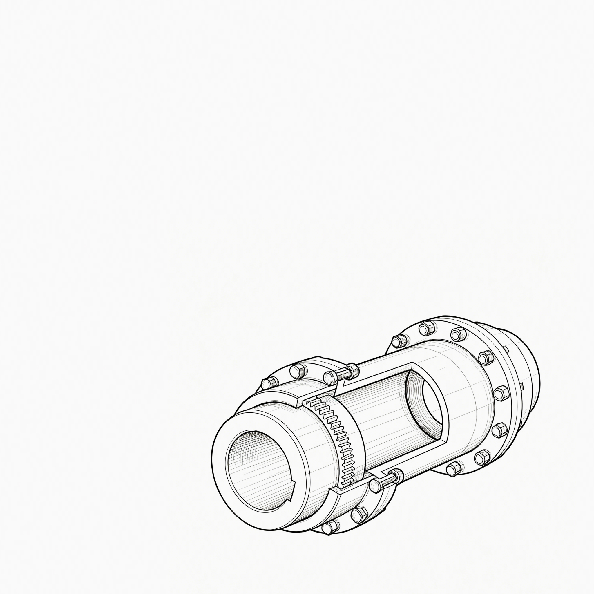
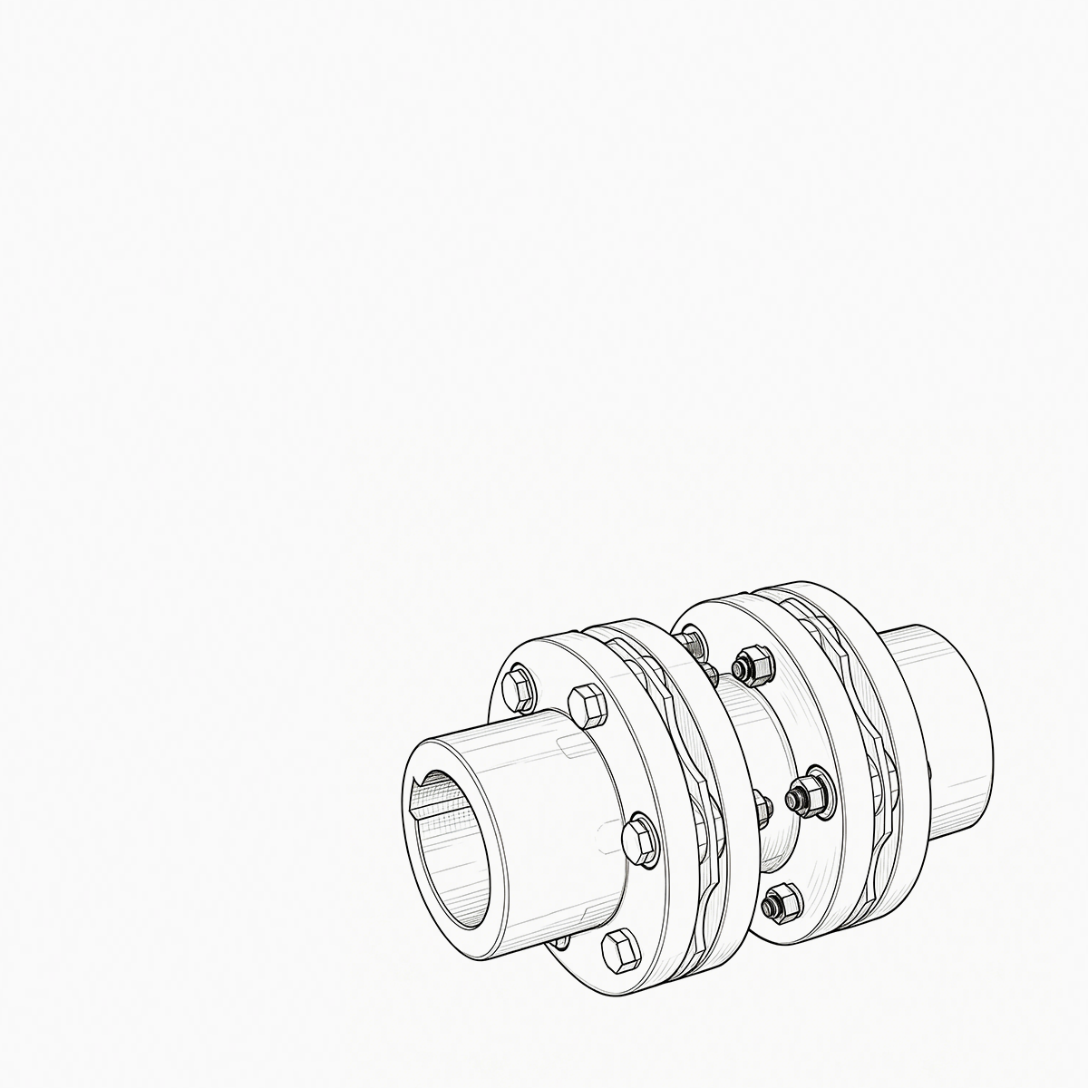
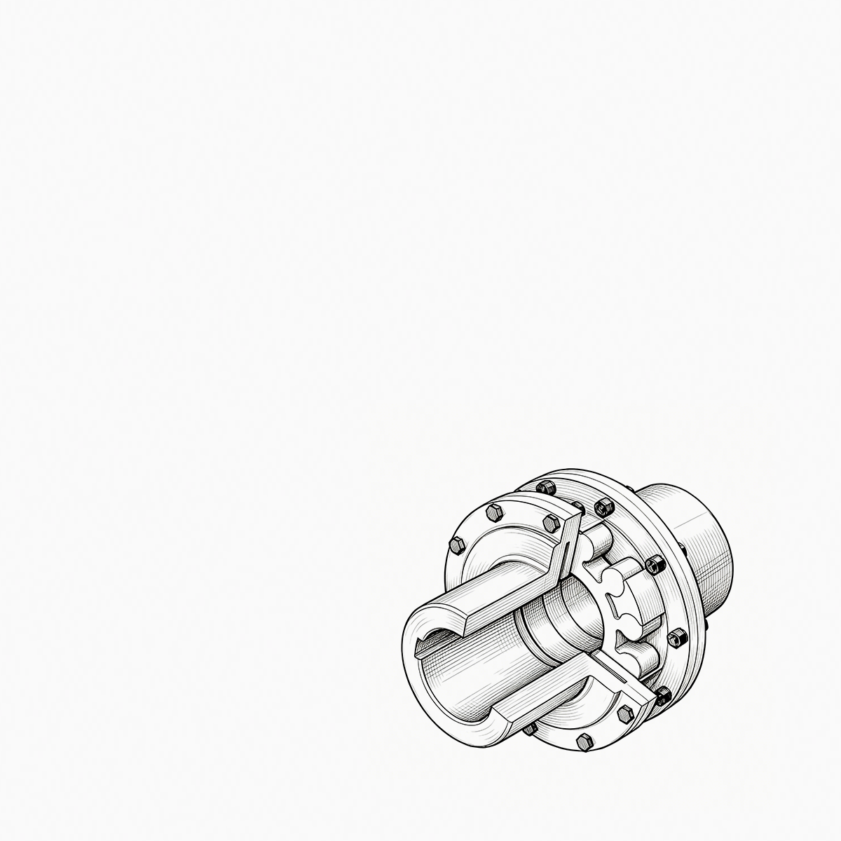
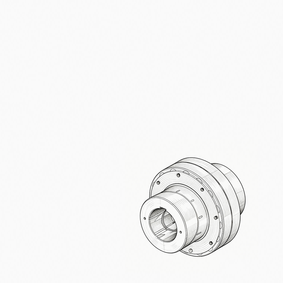
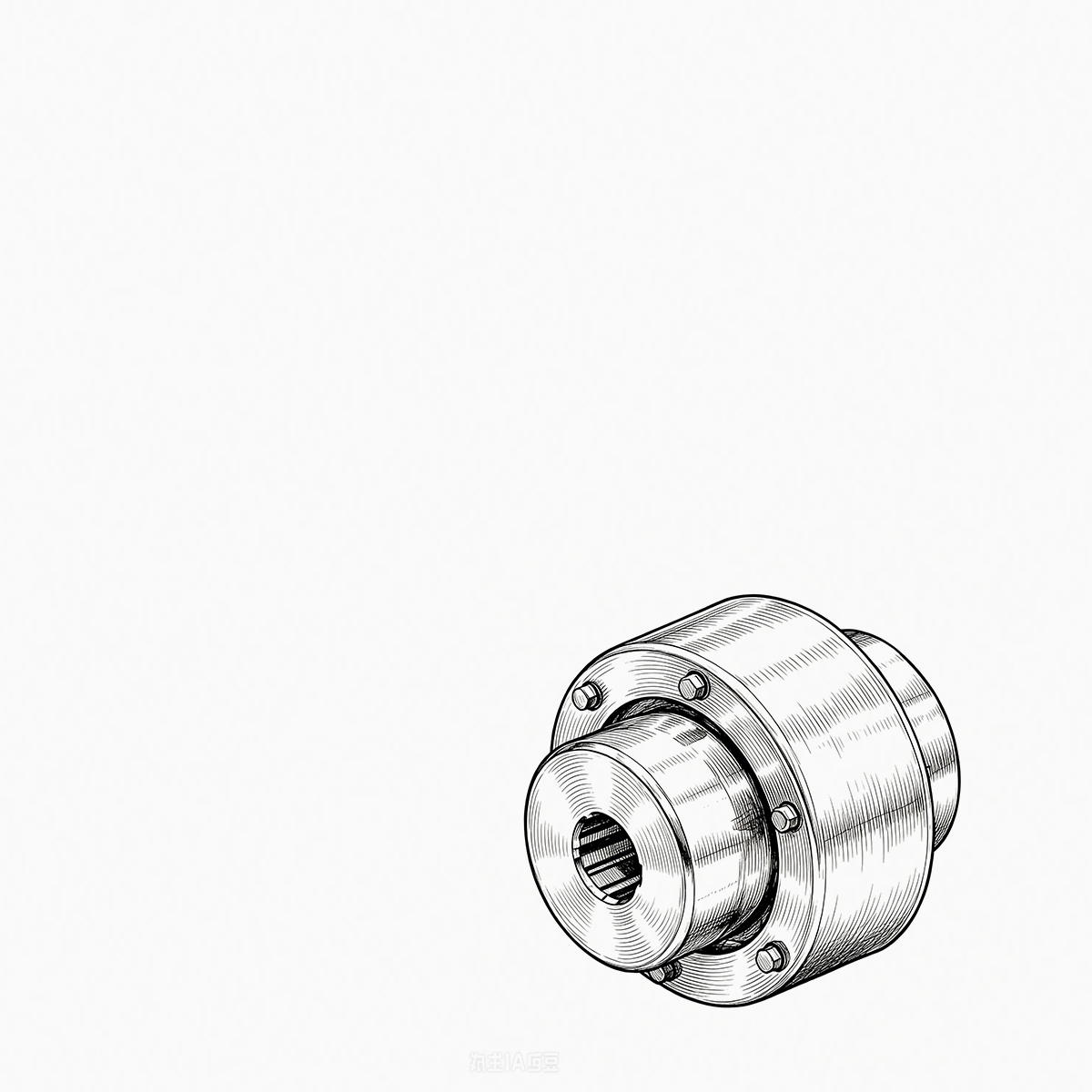
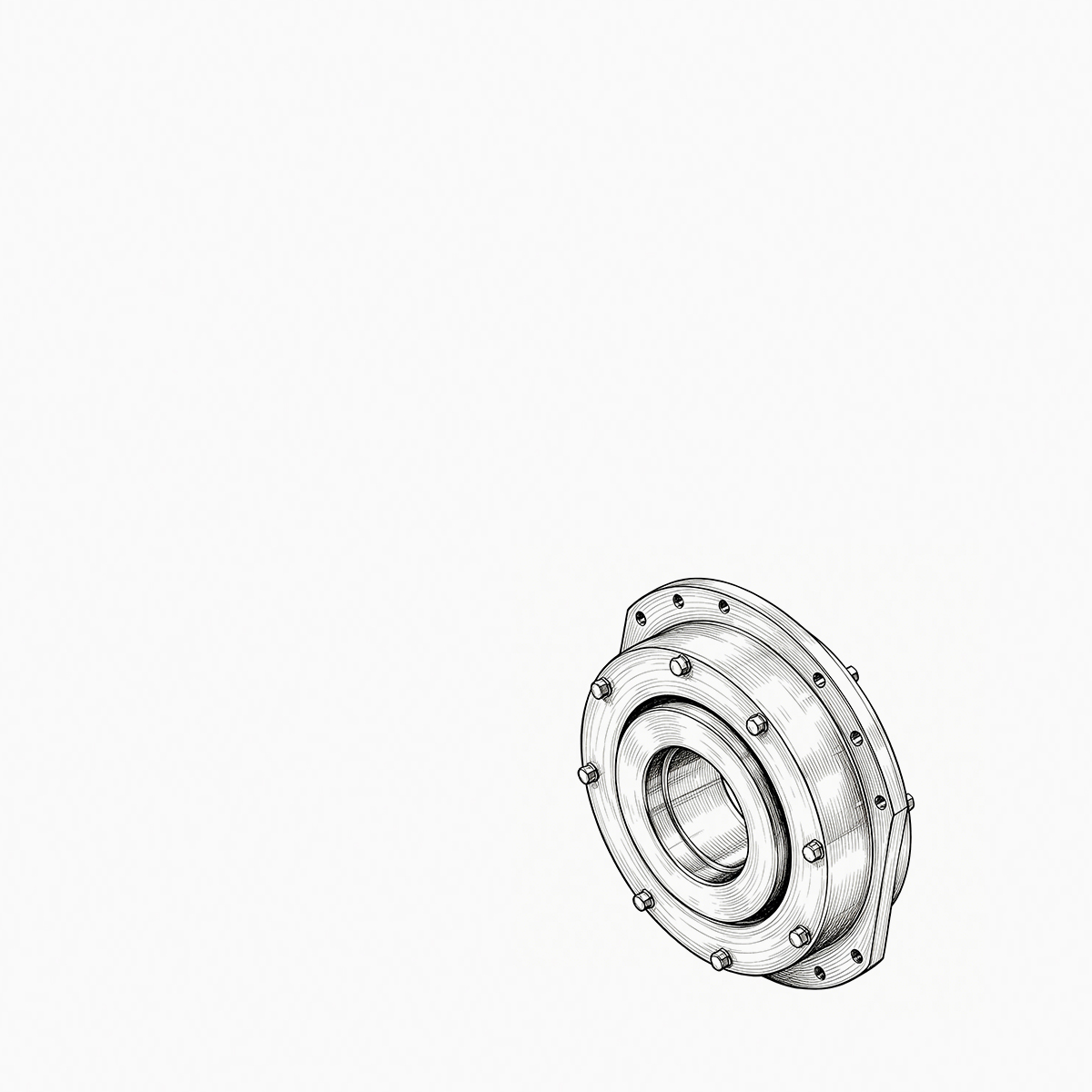
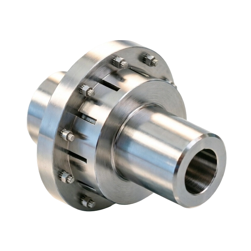
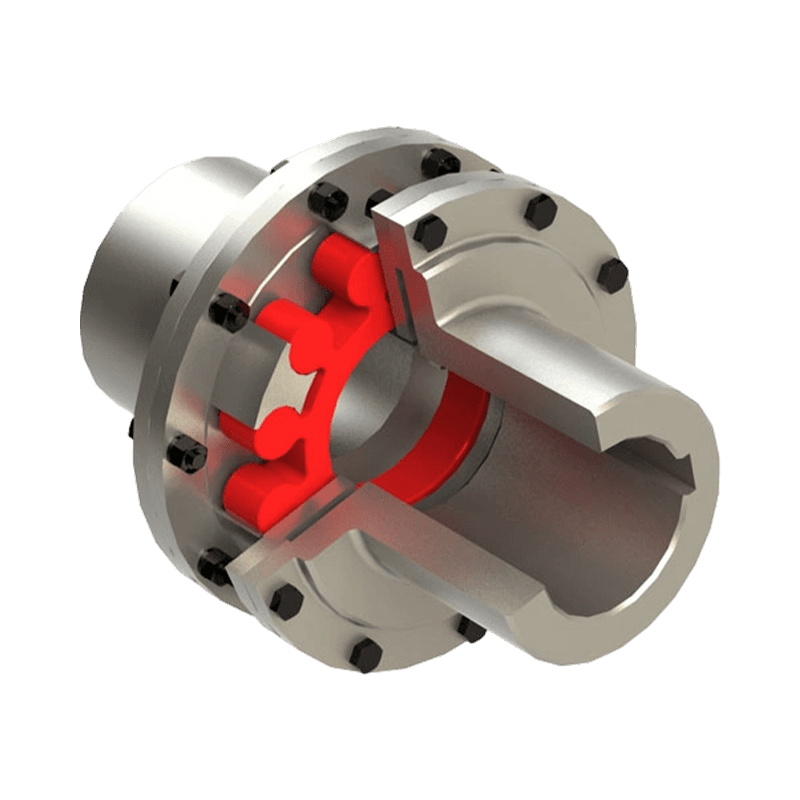
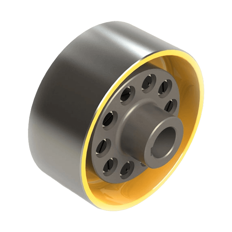
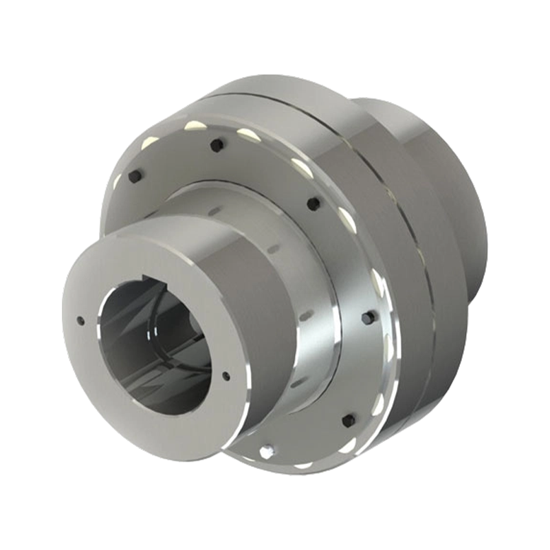
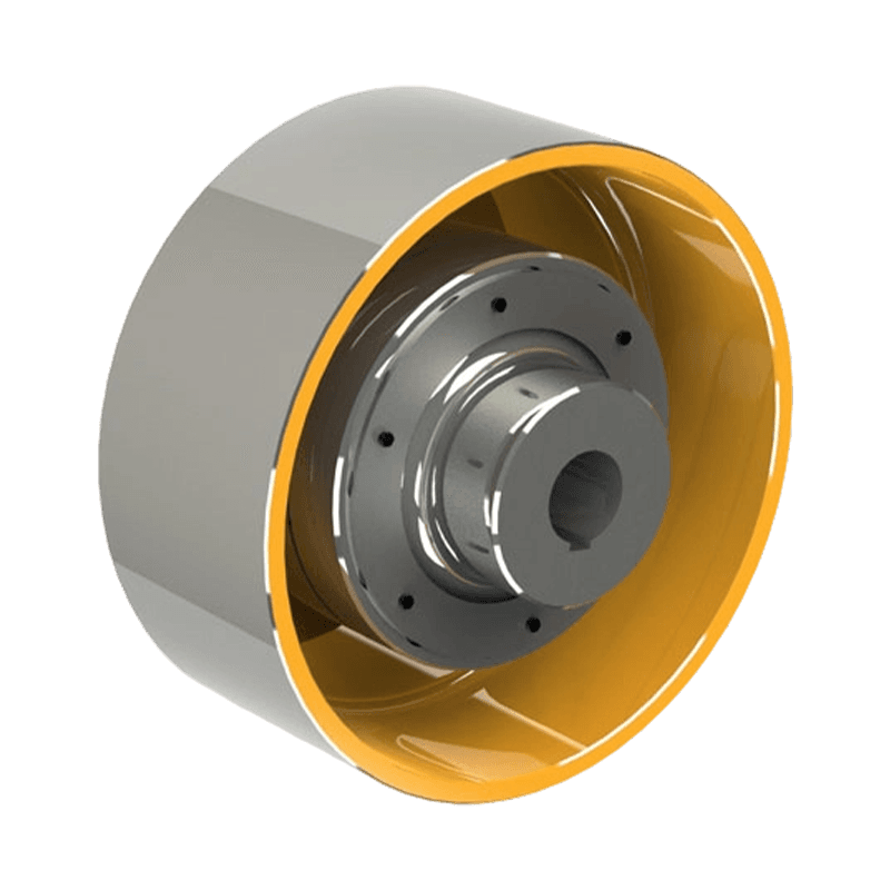
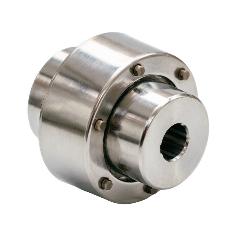
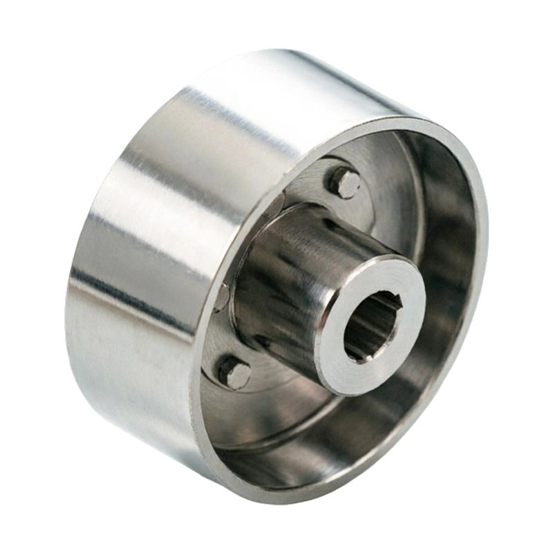
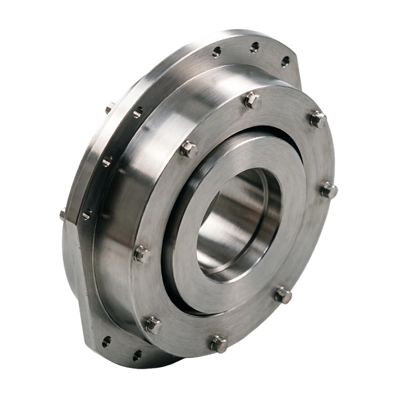

Two quotes land for the same replacement gear coupling: $1,850 from one shop and $2,600 from another. Both promise standard compliance, both quote four weeks, and the drawings look identical. The 40% gap almost never sits in the steel price. It sits in tooth geometry and heat treatment, hub bore an...
READ MORE
 Product Category
Flexible and Rigid Coupling Manufacturers
Company

Zhenjiang Orienthold Machinery Co., Ltd.
Zhenjiang Orienthold Machinery Co., Ltd. is China Flexible and Rigid Coupling Manufacturers and Mechanical Coupling Factory, We are a medium-sized enterprise specialized in the production of couplings and papermak-ing machinery, integrating design, production and service.
Boasting strong technical strength, advanced equipment and comprehensive testing methods, our products are widely used in industries and equipment such as transportation, metallurgy, chemical engineering, mining, construction and hoisting, and are supplied to various large-scale enterprises all year round.
Equipped with a strict quality supervision system as well as complete inspection and testing instruments and equipment, our products fully comply with national standards. In particular, the production technology and quality of our papermaking machinery have reached international levels. Our products have won wide praise in the market and gained high recognition from customers.
News
-
-
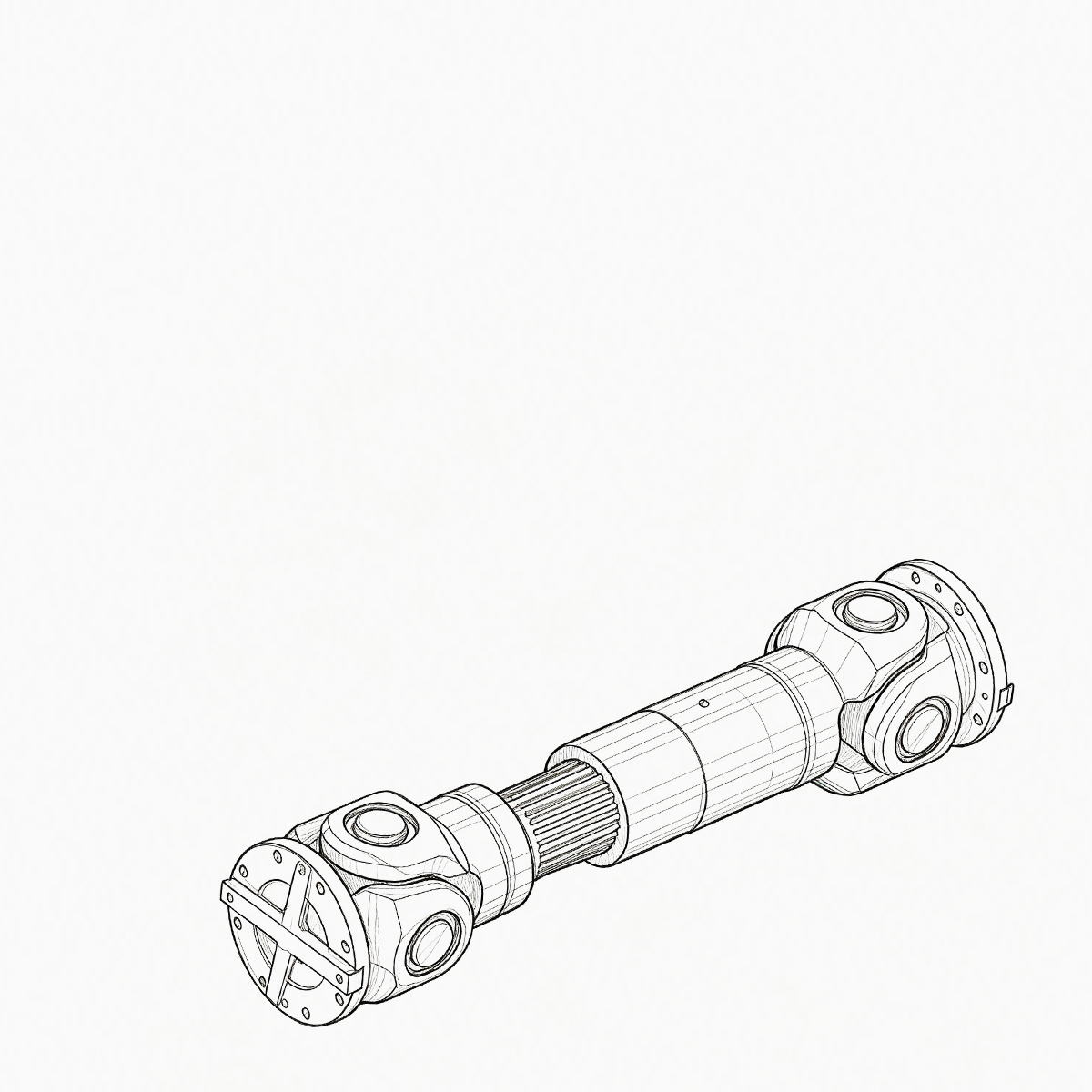
Consider a 250 kW crane hoist that begins to vibrate only when the load is lifted. The drum gear coupling is inspected after a few months and the tooth wear is concentrated on one flank. The common diagnosis is not a single defective component; it is a mismatch between the catalogue torque, the act...
READ MORE -
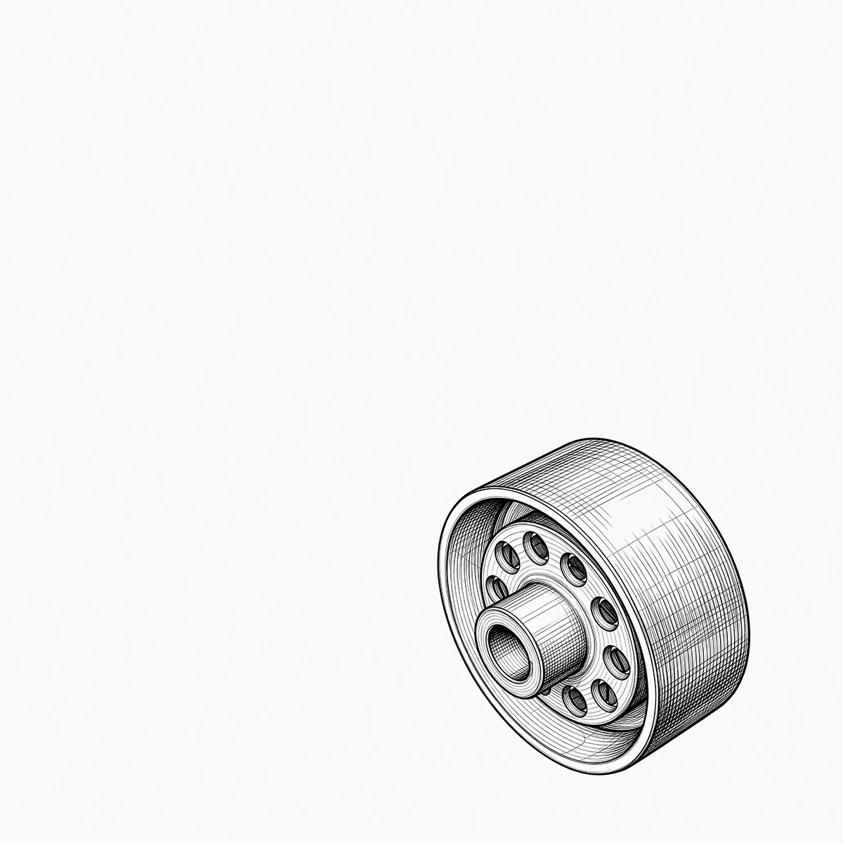
A maintenance engineer pulls a failed coupling from a pump drive. The elastomer sleeves are cracked, the pin bolts are scored, and the hub bore shows the tell-tale fretting marks of a poor fit. For most medium-duty industrial drives, the replacement is not an exotic engineering exercise: an elastic...
READ MORE
Message Feedback
Products Industry knowledge
What is the Difference Between Flexible Couplings and Rigid Couplings?
Fundamental Mechanical Operating Principles
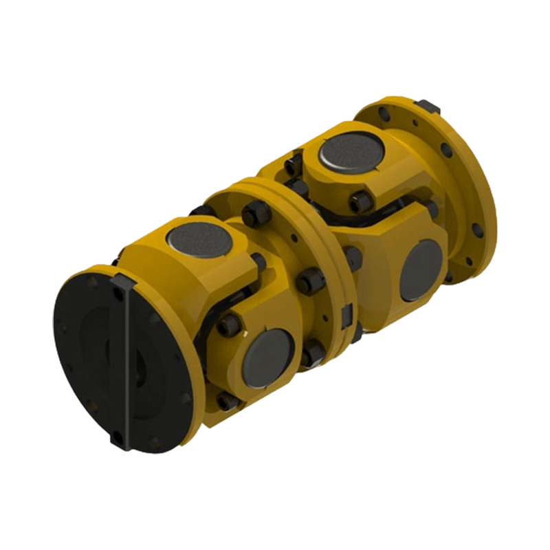
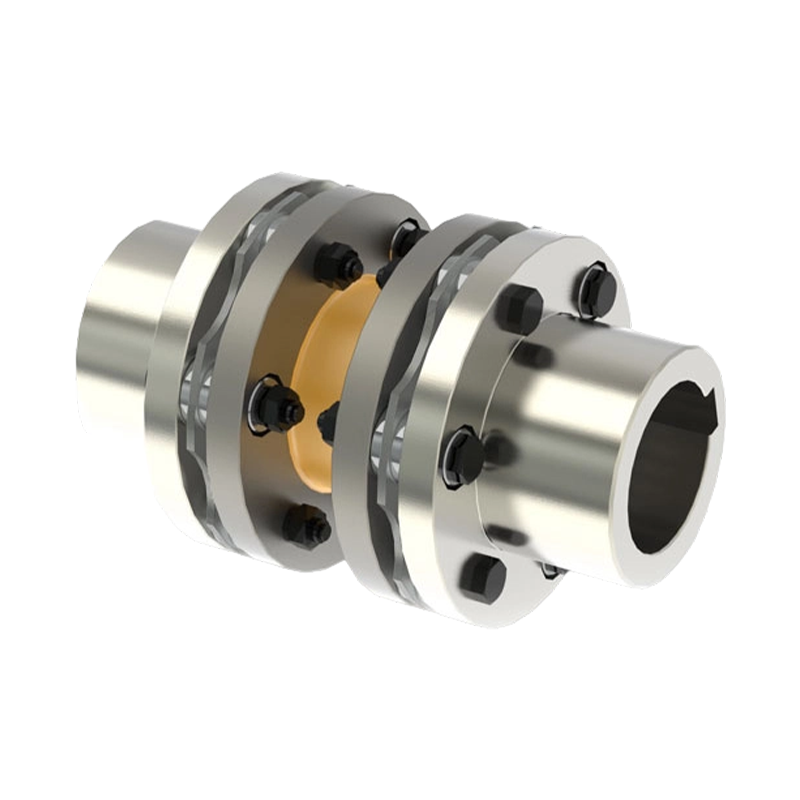
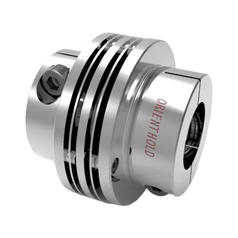
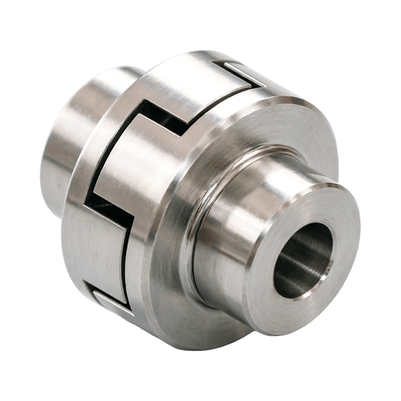
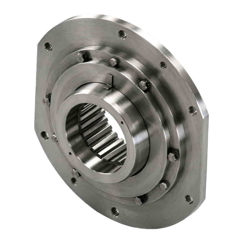
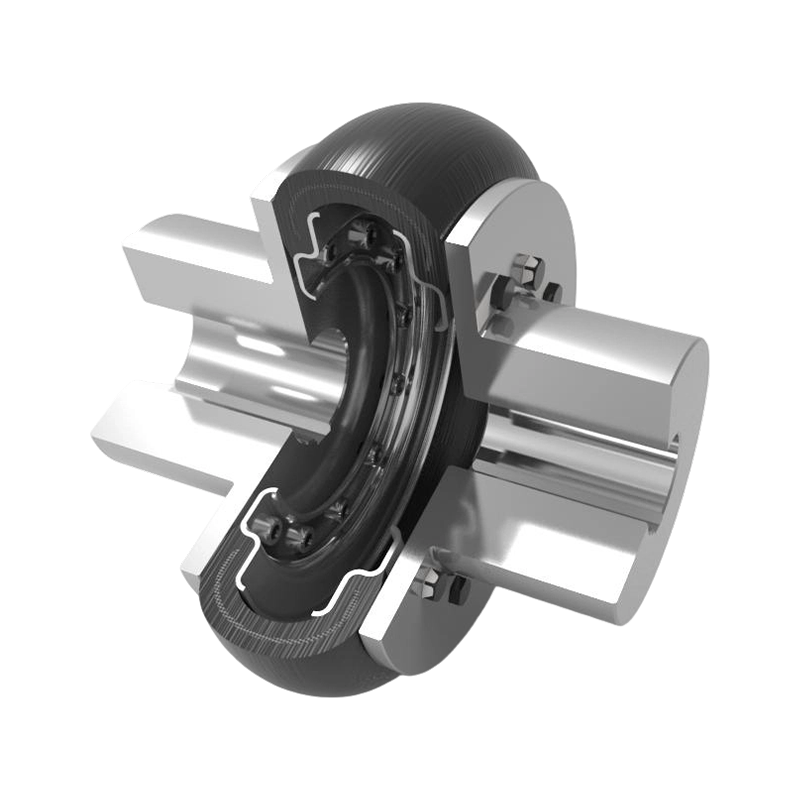
Couplings serve as essential mechanical components in industrial power transmission systems, connecting two independent shafts together to transfer rotational power from a driving machine to a driven machine. Zhenjiang Orienthold Machinery Co., Ltd. produces power transmission assemblies that highlight two main structural designs: the flexible and rigid coupling. The distinction between these two categories lies in their mechanical compliance and their ability to manage geometric irregularities between connected shafts. Rigid couplings form a fixed, solid connection that forces both shafts to act as a single continuous unit. Flexible couplings incorporate elastomeric inserts, metallic membranes, or articulated joints that permit controlled relative motion between the joined shafts without interrupting torque transmission.
Shaft Alignment Requirements and Precision Standards
Precision alignment remains a primary factor when choosing between rigid and flexible coupling designs. Rigid couplings require precise alignment between the motor and driven equipment shafts during installation. Because rigid designs offer no inherent compensation for geometric offsets, any angular misalignment, parallel misalignment, or axial displacement directly generates reaction forces on support bearings and shafts. A flexible and rigid coupling comparison highlights that flexible models are engineered to absorb combinations of parallel offset, angular deviation, and axial movement. During equipment assembly, thermal expansion, or continuous duty in heavy industrial environments, shafts inevitably experience operational movement. Flexible couplings protect surrounding components by absorbing these spatial variations through material elasticity or internal mechanical clearance.
Vibration Damping and Shock Absorption Capabilities
Industrial machinery experiences dynamic loads, torsional vibrations, and sudden impact forces during continuous operation. Flexible couplings utilize resilient materials such as polyurethane, rubber, or metallic spring elements that absorb vibration energy and dampen torsional shock loads. This vibration attenuation helps reduce operational stress on connected equipment such as gearboxes, pumps, and rolls in papermaking machinery. Rigid couplings lack dampening capabilities, transmitting shock loads, torque fluctuations, and high-frequency vibrations directly across the joint from one shaft to the other. Consequently, rigid configurations require stable, uniform loading conditions and heavy-duty mounting bases to maintain system integrity over long operating cycles.
Structural Comparison of Flexible and Rigid Coupling Systems
| Design Parameter | Flexible Coupling | Rigid Coupling |
|---|---|---|
| Misalignment Compensation | Compensates for parallel, angular, and axial offsets | Requires strict axial and radial shaft alignment |
| Vibration Attenuation | Dampens torsional vibration and shock loads | Transmits shock and dynamic vibration directly |
| Backlash and Torsional Stiffness | Variable torsional stiffness; slight backlash in some designs | High torsional stiffness with zero backlash |
| Structural Complexity | Multi-piece assembly with wearing inserts or discs | Simple solid sleeve, flange, or split-clamp construction |
| Typical Industrial Applications | Papermaking machinery, pumps, variable load drives | Line shafts, precision positioning, vertical drive systems |
Maintenance Demands and Component Longevity
Maintenance routines differ based on the internal construction of each coupling type. Rigid couplings feature simple single-piece or split sleeve constructions with no moving parts, eliminating the need for periodic lubrication or internal element replacement. Their operational lifespan depends primarily on proper initial installation alignment and maintaining secure fastener torque. Flexible couplings include wear elements, such as rubber spiders, grid springs, or gear teeth, which require regular inspection, eventual replacement, or routine lubrication depending on the specific model. While flexible designs require periodic service, they reduce overall system maintenance costs by preventing damage to expensive driven machinery and bearing assemblies.
Load Capacity and Power Transmission Efficiency
Torque transmission characteristics dictate the selection process across heavy industries including metallurgy, mining, construction, hoisting, and chemical engineering. Rigid couplings provide high torsional stiffness and precise alignment retention, transferring high torque capacities through compact physical dimensions without rotational lag or backlash. This characteristic makes rigid couplings suitable for applications where precise timing or zero rotational play is essential. The flexible and rigid coupling selection process balances this rigid precision against the flexibility needed to transmit heavy torque loads while accommodating mechanical shaft movements without causing premature fatigue to adjacent components.
Application Guidelines Across Heavy Industrial Equipment
Matching the coupling type to the operational environment ensures system stability across demanding sectors like transportation and material handling. Zhenjiang Orienthold Machinery Co., Ltd. incorporates these engineering principles across various machinery designs. Rigid couplings suit vertical drive shafts, short line shafts with solid bedplates, and applications where external alignment remains fixed throughout operation. Flexible couplings are selected for continuous-duty production lines, papermaking equipment, pumps, and hoisting machinery where thermal expansion, structural flexing, or heavy shock loads occur during daily operating cycles.
FAQ
Q: Under what specific operating conditions should a facility prioritize a flexible coupling over a rigid one?
A: A flexible coupling is necessary when the connected equipment experiences thermal expansion, structural settling, or vibration during operation. In sectors such as papermaking machinery or chemical engineering, shafts often undergo minor movements due to temperature fluctuations or heavy load variations. Zhenjiang Orienthold Machinery Co., Ltd. recommends flexible designs in these environments to prevent the premature failure of bearings and seals that would otherwise occur if the shafts were constrained by a rigid connection.
Q: How does the selection of a flexible or rigid coupling impact the maintenance schedule of heavy-duty hoisting equipment?
A: Rigid couplings require no internal maintenance or lubrication, as they contain no moving wear parts, but they demand absolute precision during initial installation to avoid mechanical stress. Conversely, flexible couplings utilize intermediate components like elastomeric spiders or grid springs which act as sacrificial elements. While these components require periodic inspection and eventual replacement, they protect the more expensive drive motors and gearboxes from shock loads, effectively reducing the total cost of ownership for high-frequency hoisting operations.
Q: Can rigid couplings be utilized in applications involving high-torque transmission without risking shaft fatigue?
A: Rigid couplings are capable of transmitting high torque with zero backlash, making them suitable for vertical drives or line shafts where the alignment remains constant. However, they lack the ability to dampen torsional vibrations. If the system experiences frequent torque spikes or impulsive loads common in mining or metallurgy, Zhenjiang Orienthold Machinery Co., Ltd. advises that rigid connections may transmit these forces directly to the bearings, potentially leading to shaft fatigue unless the entire support structure is rigid enough to negate these dynamic stresses.
Q: What limitations do rigid couplings impose on the assembly process of large-scale industrial machinery?
A: Rigid couplings require near-zero tolerance regarding parallel and angular shaft misalignment. Achieving this level of precision during the assembly of large-scale transport or processing lines often requires extensive laser alignment procedures and heavy-duty bedplates to ensure stability. Because rigid couplings cannot accommodate even slight deviations in shaft positioning, any shifting of the machinery foundation over time can result in severe binding forces that threaten the integrity of the drivetrain.
Q: How should engineers determine the appropriate coupling type for papermaking machinery where moisture and heat are constant factors?
A: For papermaking machinery, engineers must account for the expansion of rollers and the constant vibration from high-speed processing. A flexible coupling is typically selected because its materials—often chosen for chemical and thermal resistance—can absorb the resulting axial and radial displacement. Zhenjiang Orienthold Machinery Co., Ltd. provides specialized coupling solutions that maintain performance stability under these demanding environmental conditions, ensuring that power transmission remains consistent despite the dynamic nature of the paper production process.
Q: Are there specific installation tolerances that differentiate the performance of flexible and rigid coupling assemblies?
A: Rigid couplings demand precise geometric alignment, as they rely on a solid, bolted connection to maintain shaft concentricity; any deviation acts as a mechanical lever against the bearings. Flexible couplings offer a wider tolerance window, as the internal flexible elements are designed to compensate for angular, parallel, and axial misalignment. While flexible designs allow for easier field installation, they should still be aligned as accurately as possible to maximize the service life of the flexible internal components.


ABOUT US
PRODUCTS
INDUSTRIES
CONTACT US
- Phone: +86-18652865511
- Email: sales@ohmach.com
- Address: No.1, Minying Developing Zone, Zhenjiang, Jiangsu, China
Copyright Zhenjiang Orienthold Machinery Co., Ltd. All Rights Reserved.
 OEM/ODM Flexible and Rigid Coupling Factory