 English
 русский
 Português
 عربى
عربى
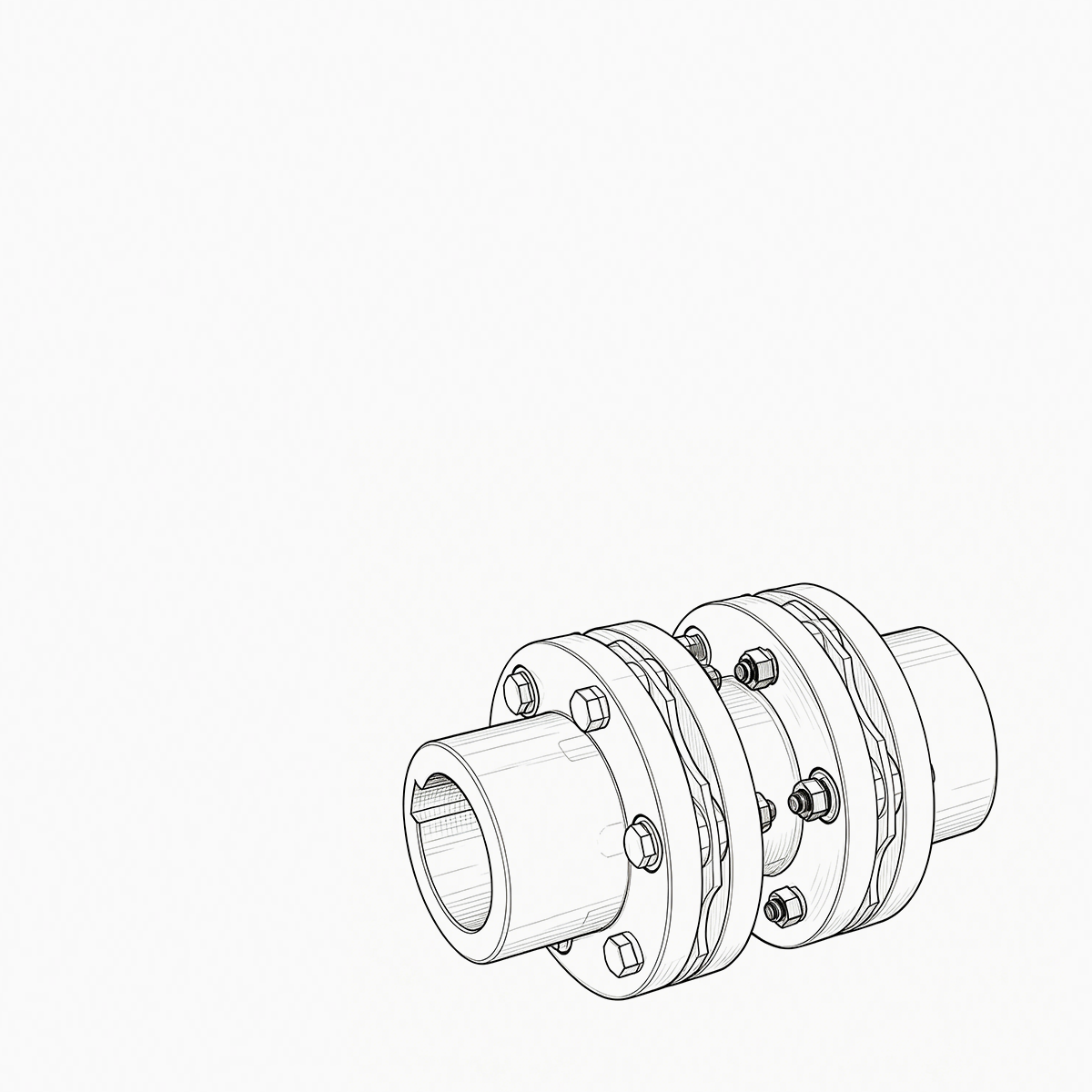
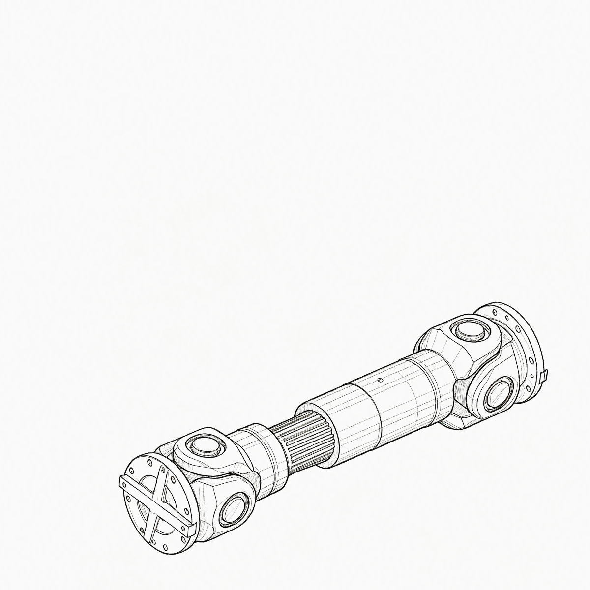
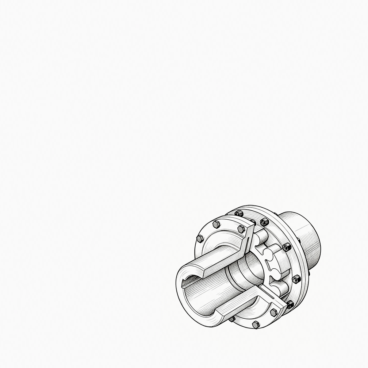
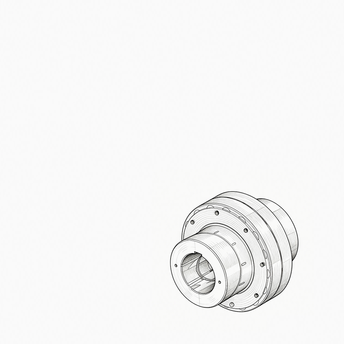
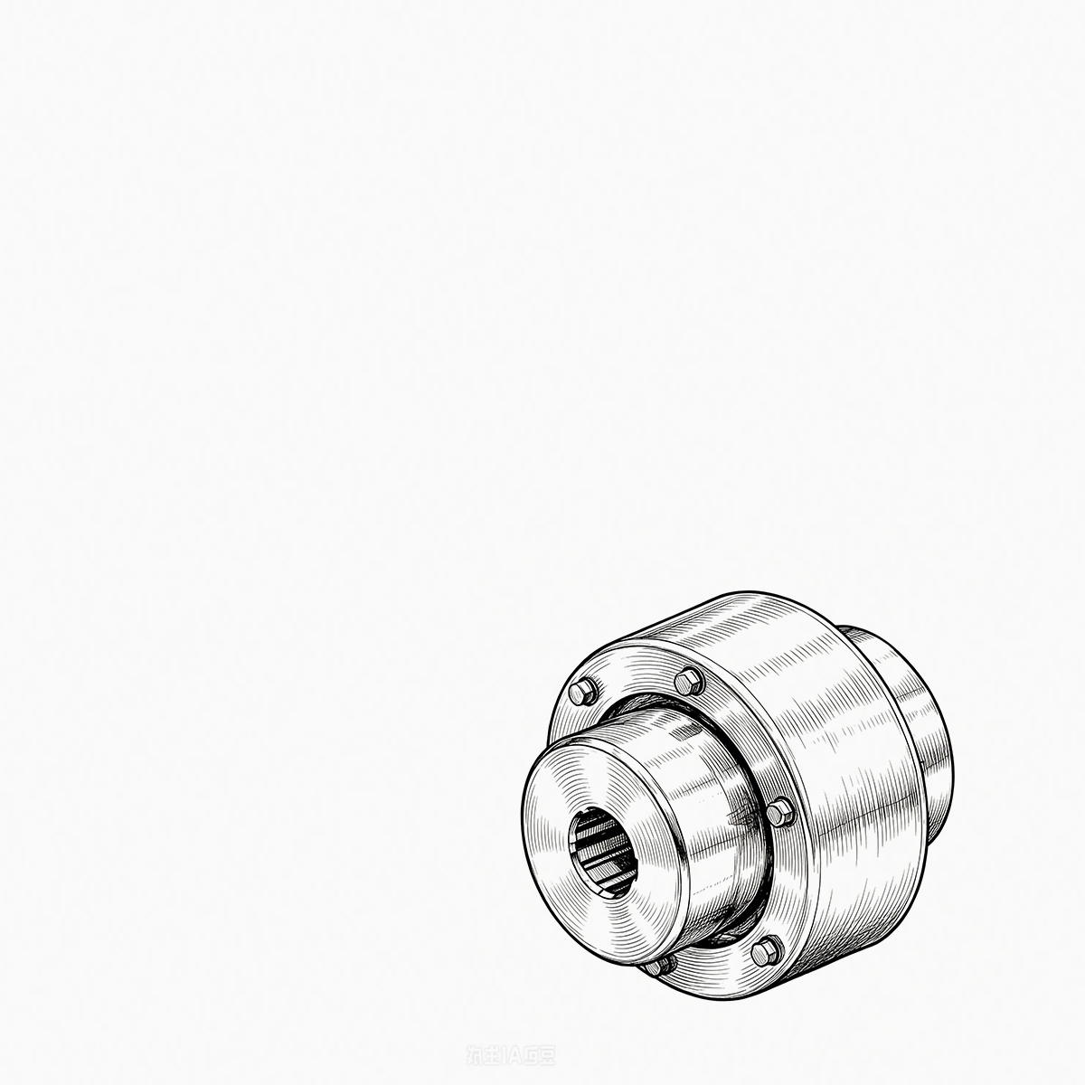
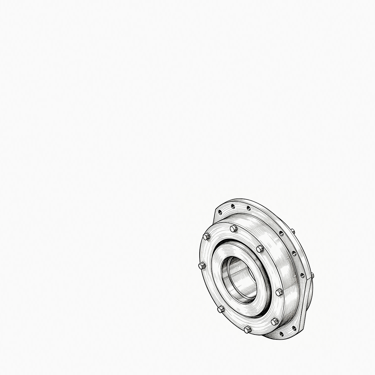
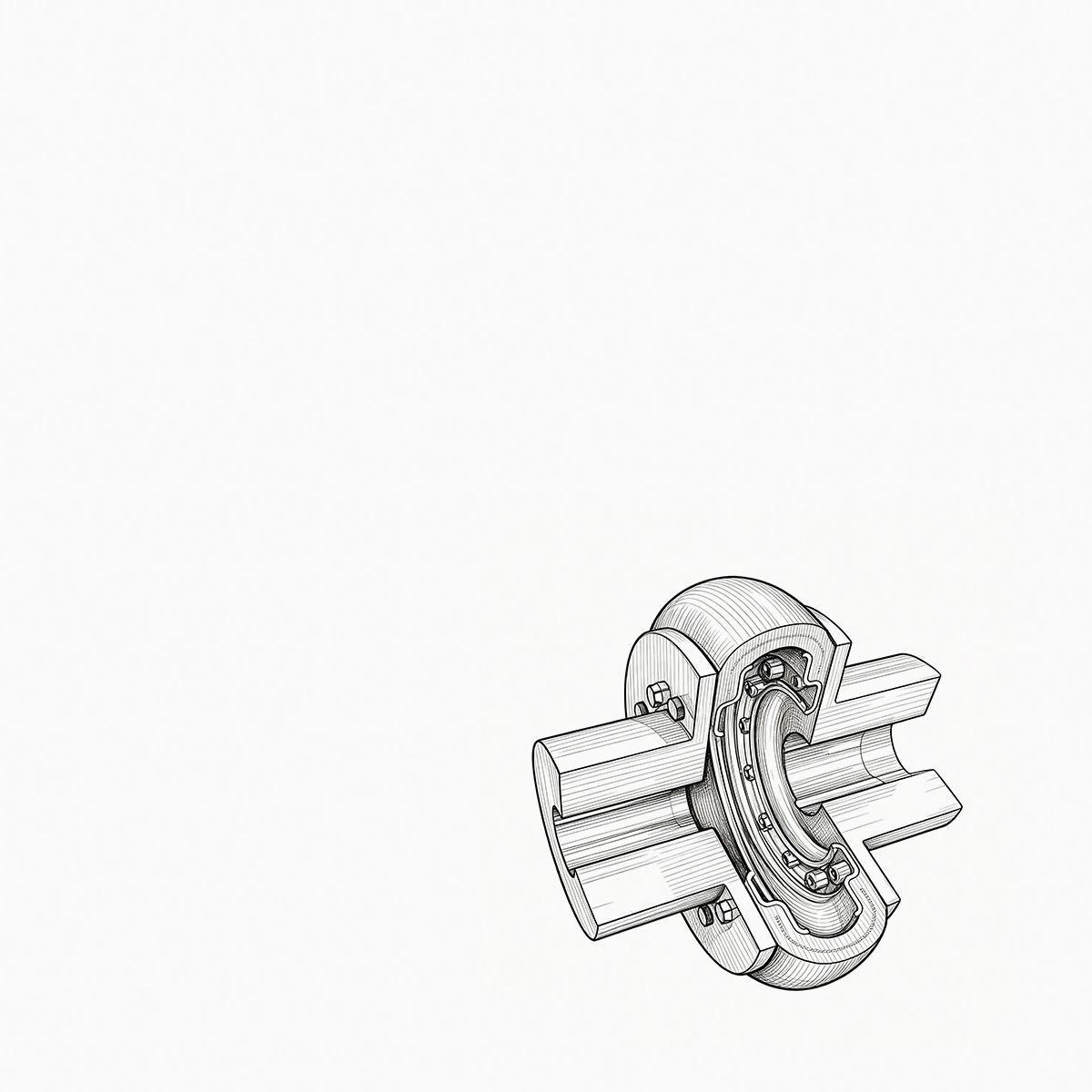


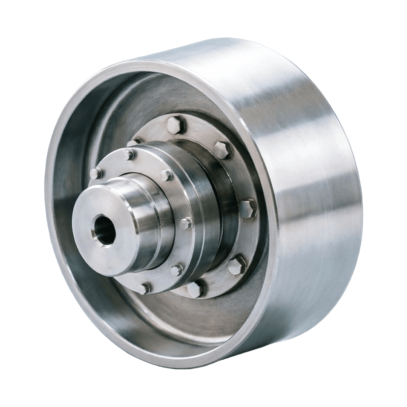
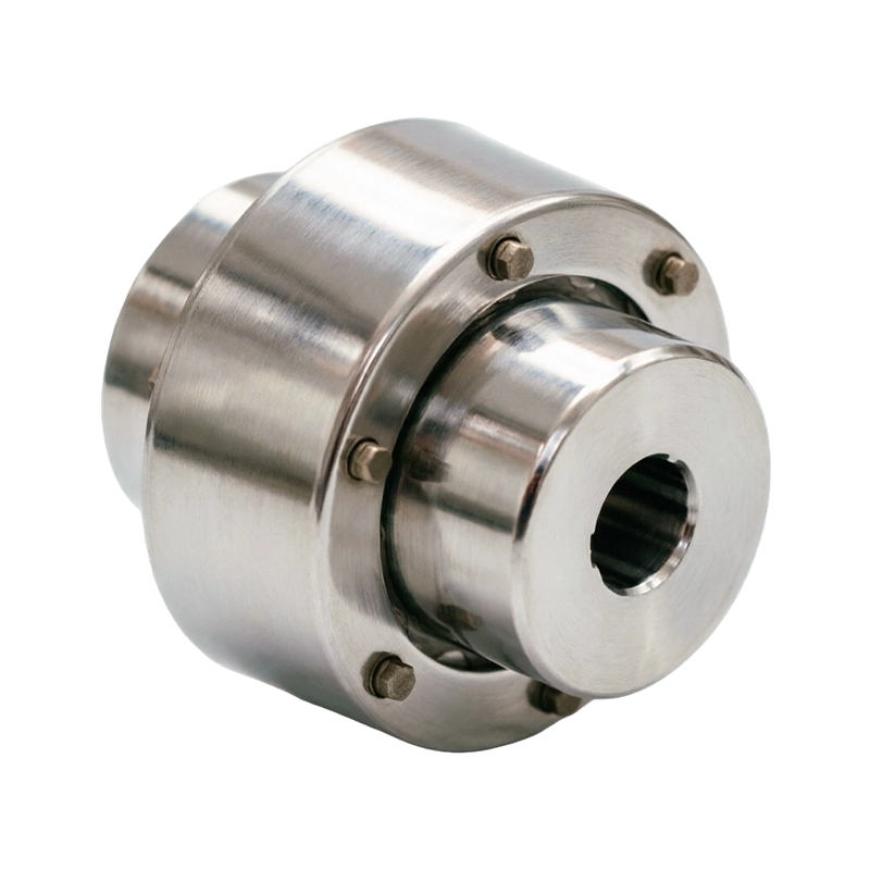
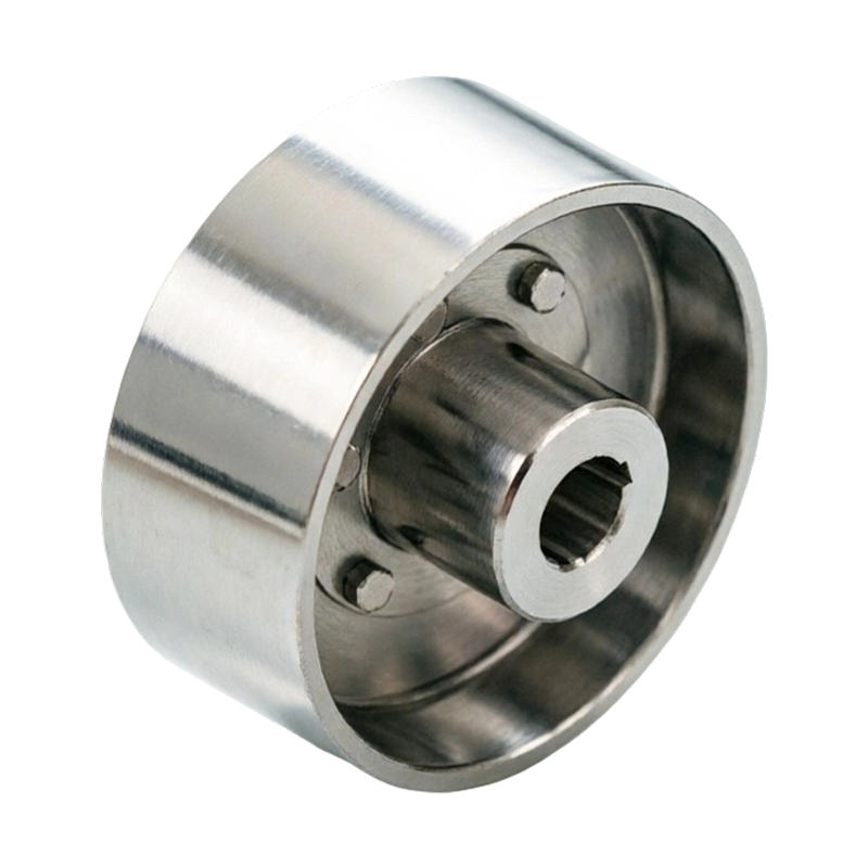
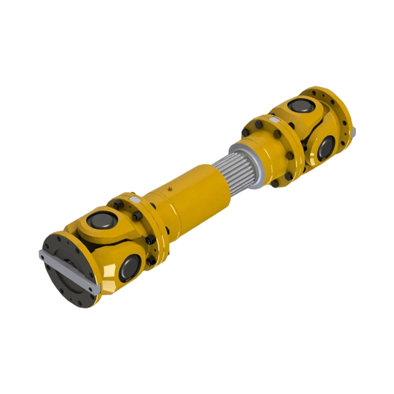
Gear Coupling vs. Drum Gear Coupling: The Core Difference The main difference is that "gear coupling" is a broad catego...
READ MORE
Drum Gear Coupling Selection: Types, Misalignment, Torque and Applications
Admin 2026-10-01Content
- 1 What a drum gear coupling does and why the crowned tooth matters
- 2 Select by torque, speed, and shaft geometry
- 3 Align the installation and estimate effective misalignment
- 4 Lubrication and maintenance: where drum gear couplings wear
- 5 Choose the right drum gear coupling variant
- 6 Drum gear couplings in industrial applications
- 7 Final selection checklist
Consider a 250 kW crane hoist that begins to vibrate only when the load is lifted. The drum gear coupling is inspected after a few months and the tooth wear is concentrated on one flank. The common diagnosis is not a single defective component; it is a mismatch between the catalogue torque, the actual misalignment, and the grease film. The reliable way to specify a drum gear coupling is to treat torque, tooth profile, shaft fit, and maintenance as one complete selection logic.
What a drum gear coupling does and why the crowned tooth matters
A drum gear coupling transmits torque through a set of crowned external teeth on each hub that mesh with internal teeth in a sleeve. The word drum refers to the curved tooth form in the axial direction. That curve allows the hub to move through a small angular offset inside the sleeve without forcing the full load onto one edge of the tooth.
Straight-tooth gear couplings are still used where alignment is closely controlled and minimal lost motion is required. In heavy industrial drives, the drum tooth profile is usually the safer choice because it increases the usable angular misalignment range and distributes contact pressure along a broader tooth surface. Most standard drum gear couplings tolerate angular misalignment of approximately 0.5 to 1.5 degrees, plus a limited amount of parallel and axial displacement. For more detail on the boundary between designs, our straight-tooth gear-coupling comparison explains the practical differences.
A gear coupling does not cancel misalignment; it accommodates misalignment through controlled sliding between the tooth sets. If a large offset is treated as a routine condition, the contact pressure and wear rate climb quickly. That is why the crowned tooth form, the sleeve fit, and the lubrication type are inseparable from the selection decision.
Select by torque, speed, and shaft geometry
Start from the duty, not from the shaft diameter alone. The nominal torque transmitted by a direct drive can be estimated as T(Nm)=9550 x P(kW)/n(rpm). For a 200 kW motor at 980 rpm, that is roughly 1950 Nm. If the driven machine has shock loads, frequent starts, or reversing duty, multiply this nominal value by a service factor. A starting point is 1.75 for moderate shock and 2.5 or higher for heavy reversing duty. The coupling size must be rated above this adjusted torque.
After torque, check the bore range. A coupling can meet the torque rating on paper and still fail early if the hub bore is near its maximum limit with an undersized keyway, or if the shaft fit cannot resist reversal forces. The outside diameter and the length of the hub must also fit the available space around the shaft.
Build a short selection checklist for the design department:
- Motor or engine power and full-load speed.
- Duty cycle: continuous, frequent starts, reversing, or braking.
- Shaft diameters, keyway dimensions, and hub clearance limits.
- Space available for the coupling outside diameter and for sleeve removal during maintenance.
- Expected misalignment from thermal expansion, base settling, bearing clearances, and pipe loads.
For a standard horizontal motor-to-gearbox drive, the basic GICL drum gear coupling is usually the first variant to check.
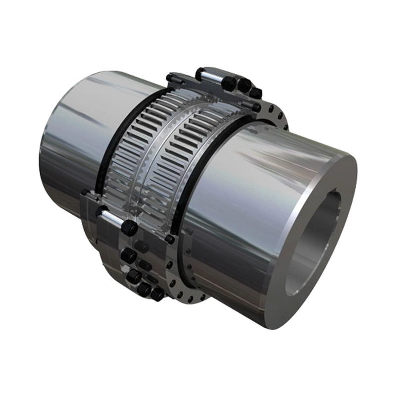 GICL Drum Gear Coupling for Horizontal Motor-to-Gearbox DrivesThis heavy-duty coupling uses crowned gear teeth to handle low-speed, high-torque operation while compensating for axial, radial, and angular misalignment. It is a practical first choice to evaluate for standard horizontal drive configurations.View Product →
The service-factor table below is a starting estimate; the final value should come from the duty analysis and the coupling manufacturer's rating.
| Duty class | Representative machines | Suggested service factor |
|---|---|---|
| Uniform | Light conveyors, machine tools, small pumps | 1.25 to 1.50 |
| Moderate shock | Piston pumps, crane travel, mixers | 1.75 to 2.25 |
| Heavy shock | Crushers, rolling mill pinions, reversing drives | 2.50 to 3.00 |
Align the installation and estimate effective misalignment
Drum gear couplings tolerate misalignment, but their life depends on how often the teeth slide and how much pressure is carried at the contact point. Angular misalignment creates sliding between the external and internal teeth; parallel misalignment moves the contact point and adds bending load to the sleeve.
In a new installation, get the shafts as close to true alignment as possible and then mount the coupling. Foundation settlement, thermal growth in the machine housing, and bearing deflection will consume some of the allowable values before the coupling even starts. Leave a margin, not just a nominal catalogue number.
A drum gear coupling is not a universal joint. If the machine design requires large articulation, a cross universal coupling or a diaphragm coupling is a more appropriate class. A gear coupling is the right choice when the drive needs a compact, torsionally stiff connection with controlled float and predictable lubrication.
Lubrication and maintenance: where drum gear couplings wear
Because a drum gear coupling transmits torque through sliding tooth contact, the grease is part of the design. The tooth cavity should be packed with an extreme-pressure grease that stays in place under running conditions and remains stable at the expected operating temperature. Many standard drives use an NLGI grade 1.5 or 2 grease with a synthetic or lithium thickener. Dusty sites, splash water, and high ambient temperatures require a grease with better water resistance and EP protection.
Relubrication intervals depend on speed, temperature, and load cycles. A high-speed coupling may need grease every few months, while a slow heavy-duty unit can sometimes run longer, but the manufacturer's schedule is the starting point. If you change grease type, purge the old grease first; incompatible thickeners can harden and restrict tooth clearance.
Inspection should include the wear pattern on both external and internal teeth. Even wear across the tooth width is healthy. Wear concentrated on one edge indicates that the actual misalignment is higher than the design value. Discolored grease or a metallic grey paste in the tooth cavity usually points to overloading, insufficient relubrication, or loss of the grease film.
Choose the right drum gear coupling variant
The term drum gear coupling covers a full family of constructions. The most economical versions are intended for horizontal motor-to-gearbox drives with normal access for alignment and greasing. When the drive train includes a brake, a vertical shaft, or a large gap between the machines, a purpose-designed variant is a better choice than a basic coupling adapted on site.
| Variant | Typical use | Selection note |
|---|---|---|
| Basic GICL / WG type | Standard horizontal drives, motor-gearbox and mill shafts | Use when no brake or spacer feature is required. |
| WGC vertical type | Vertical pumps, mixers, inclined shafts | Confirms lubrication retention and tooth contact when one shaft is vertical. |
| WGZ with brake wheel | Hoists, winches, crane mechanisms | Combines the coupling and drum brake housing in one package. |
| WGP with brake disc | Drives using a separate disc brake | Suits applications where a disc-brake system is mounted axially. |
| WGT with intermediate spacer | Pumps and motors with a large shaft gap | Permits the spacer to be removed and the pump serviced without moving the driver. |
| DC / WJ / WZL crane series | Crane travel, luffing, and slewing drives | Designed for crane load spectrum, shock, and enclosed drive trains. |
On hoisting or winch drives where a drum brake is already part of the machine, a coupling with an integrated brake wheel shortens the drive train and keeps the brake surface concentric with the shaft.
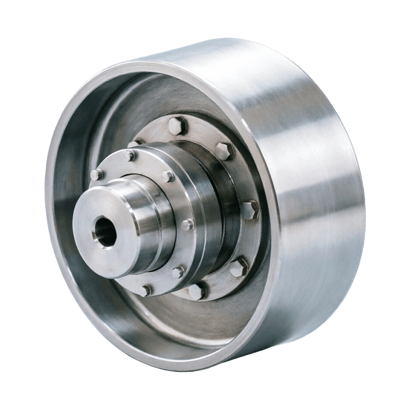 WGZ Coupling with Integrated Brake Wheel for Hoisting MachineryFeaturing a crowned gear design and an integrated brake drum, this coupling combines torque transmission with braking in one compact unit. It suits hoisting and winch drives where a separate brake assembly would complicate the drive train.View Product →
For vertical pump or mixer shafts, check the vertical drum gear coupling design rather than assuming that any gear coupling can be mounted upright without changing lubrication retention. For pump maintenance, a spacer coupling lets the pump be pulled back without moving the motor.
Drum gear couplings in industrial applications
Drum gear couplings appear in almost every heavy shaft train where a compact, torsionally stiff connection is needed. In steel and metallurgy, they connect pinion stands and roller-table drives where vibration and torque peaks are common. In petrochemical plants and power generation, they transmit torque through pumps, fans, and blowers where alignment can shift as pipe loads develop. On marine installations, easy service and resistance to corrosion determine the design. In mining, dust and water make sealed lubrication and robust tooth surfaces important.
Hoisting equipment is a special case because the drive is short, reversing, and often combined with a braking device. Drum gear couplings handle this well when the variant matches the crane duty. Because cranes have specific load cycles and safety factors, the crane drum coupling series is sized more conservatively. The hoisting and construction machinery overview gives a useful starting point for these applications; for a compact crane drive with an integrated brake option, the DC-type crown-edge drum coupling is a typical choice.
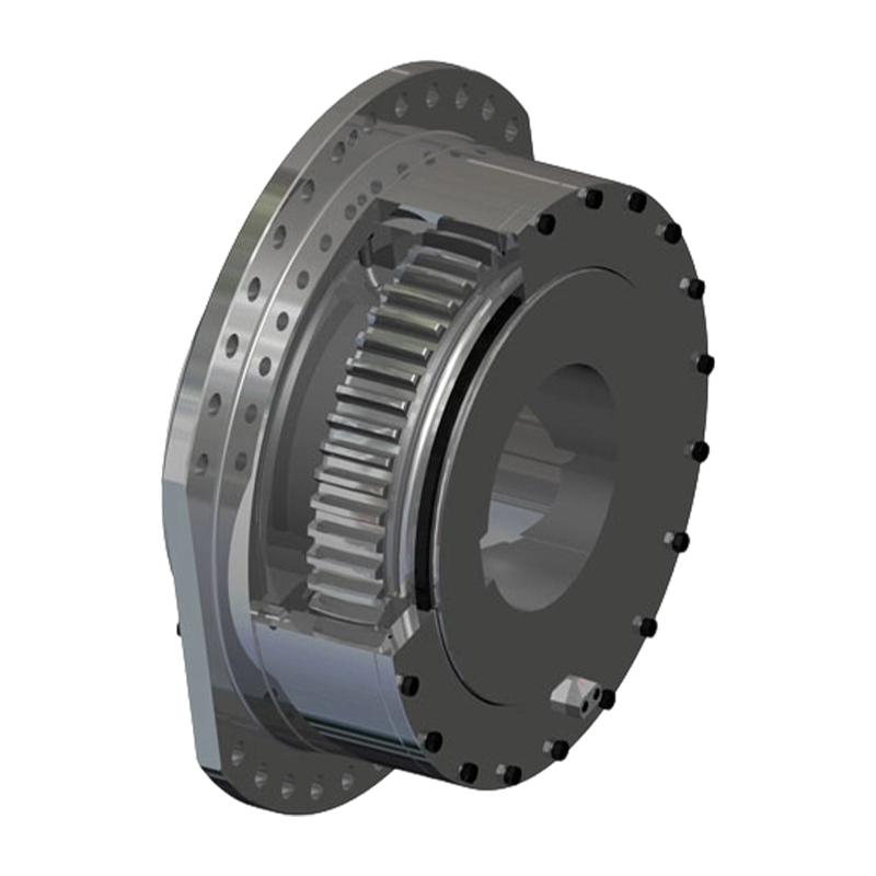 DC Crowned-Gear Drum Coupling for Crane Hoisting SystemsDesigned specifically to couple reducers to drums in hoisting applications, this coupling handles high radial loads and torque with a self-aligning spherical bearing. It is a typical choice for compact crane drives with integrated braking options.View Product →
Final selection checklist
The final decision should be made from a sizing table with the real duty data in front of you. The common mistakes are using shaft diameter as the only sizing input, ignoring locked-torque or stall conditions, and expecting more misalignment capacity than the coupling can deliver without accelerated wear.
- Use the adjusted torque with the correct service factor.
- Check that the shaft diameter and keyway are inside the catalogue range.
- Choose the construction variant that matches the brake, spacer, vertical, or crane requirements.
- Define the alignment target for installation and make a final alignment record.
- Set a relubrication schedule and include tooth condition in the inspection checklist.
A drum gear coupling can give a long service life if it is selected for the actual duty, lubricated as a loaded mechanical component, and protected from excessive installation misalignment. That combination is what turns a standard component into a reliable part of a production line.
PREV: Gear Coupling Manufacturers: How to Choose a Reliable Industrial SupplierNEXT: A Guide to Selecting, Fitting, and Maintaining Elastic Sleeve Pin Couplings
Be the First to Know
For exclusive deals and latest offers, sign up by entering your email address below.
Related products
News
-
-
During a routine vibration survey on a high-speed compressor train, engineers found a 4.5 mm/s velocity spike at the mo...
READ MORE -
Two quotes land for the same replacement gear coupling: $1,850 from one shop and $2,600 from another. Both promise stan...
READ MORE -
China's coupling industry is at a critical historical juncture of transformation from scale expansion to quality and eff...
READ MORE -
Your compressor train is running at 9,800 rpm when the vibration monitor triggers an alarm. The first component your ma...
READ MORE -
A maintenance engineer pulls a failed coupling from a pump drive. The elastomer sleeves are cracked, the pin bolts are ...
READ MORE


ABOUT US
PRODUCTS
INDUSTRIES
CONTACT US
- Phone: +86-18652865511
- Email: sales@ohmach.com
- Address: No.1, Minying Developing Zone, Zhenjiang, Jiangsu, China
Copyright Zhenjiang Orienthold Machinery Co., Ltd. All Rights Reserved.
 Custom Industrial Shaft Coupling Manufacturers