 English
 русский
 Português
 عربى
عربى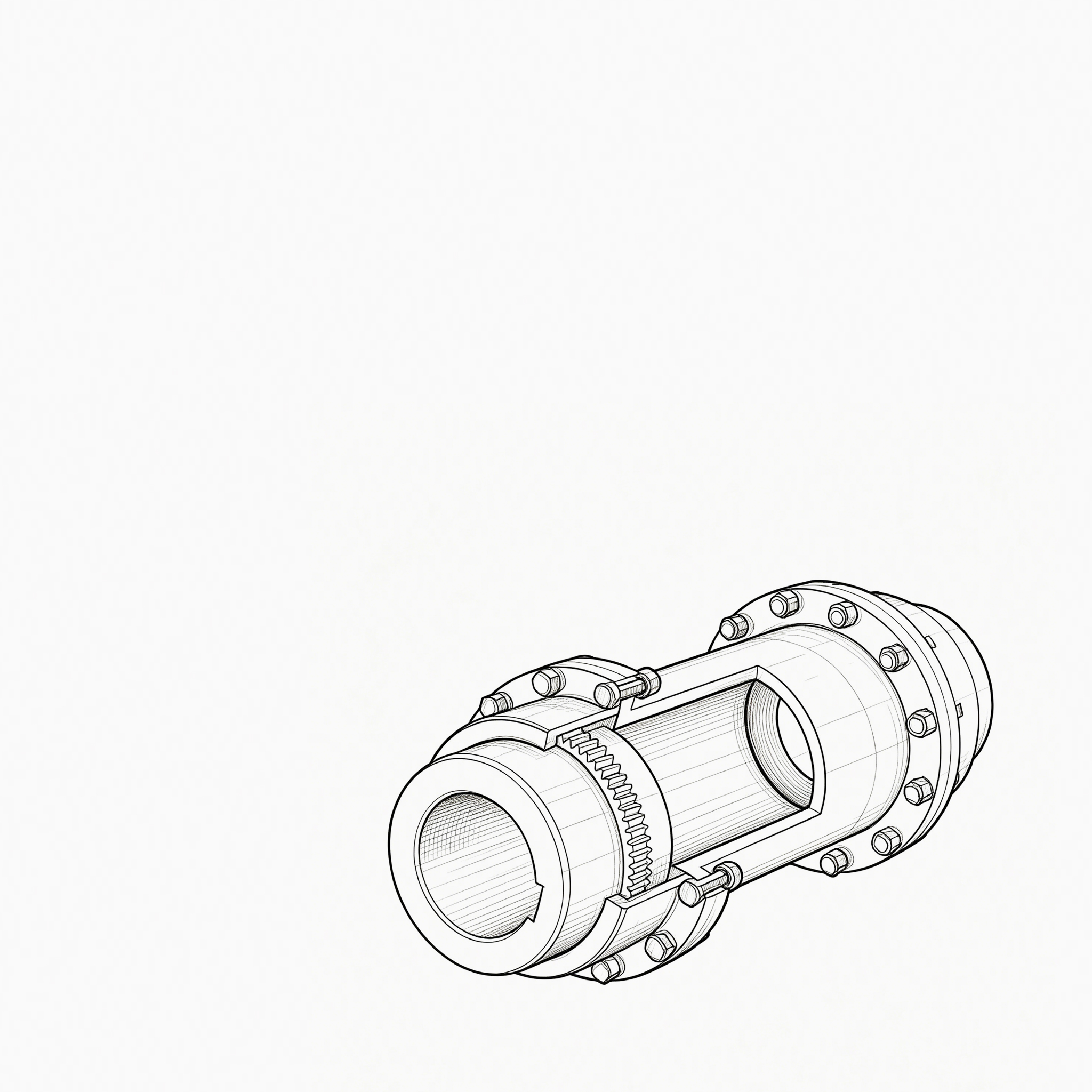


Two quotes land for the same replacement gear coupling: $1,850 from one shop and $2,600 from another. Both promise stan...
READ MORE
Gear Coupling vs. Drum Gear Coupling: Key Differences Explained
Admin 2026-08-19Content
- 1 Gear Coupling vs. Drum Gear Coupling: The Core Difference
- 2 How Each Coupling Type Is Constructed
- 3 Misalignment Capacity and Torque Handling
- 4 Installation, Space, and Maintenance Considerations
- 5 Typical Applications for Each Coupling Type
- 6 Cost and Lifecycle Comparison
- 7 How to Choose Between the Two
Gear Coupling vs. Drum Gear Coupling: The Core Difference
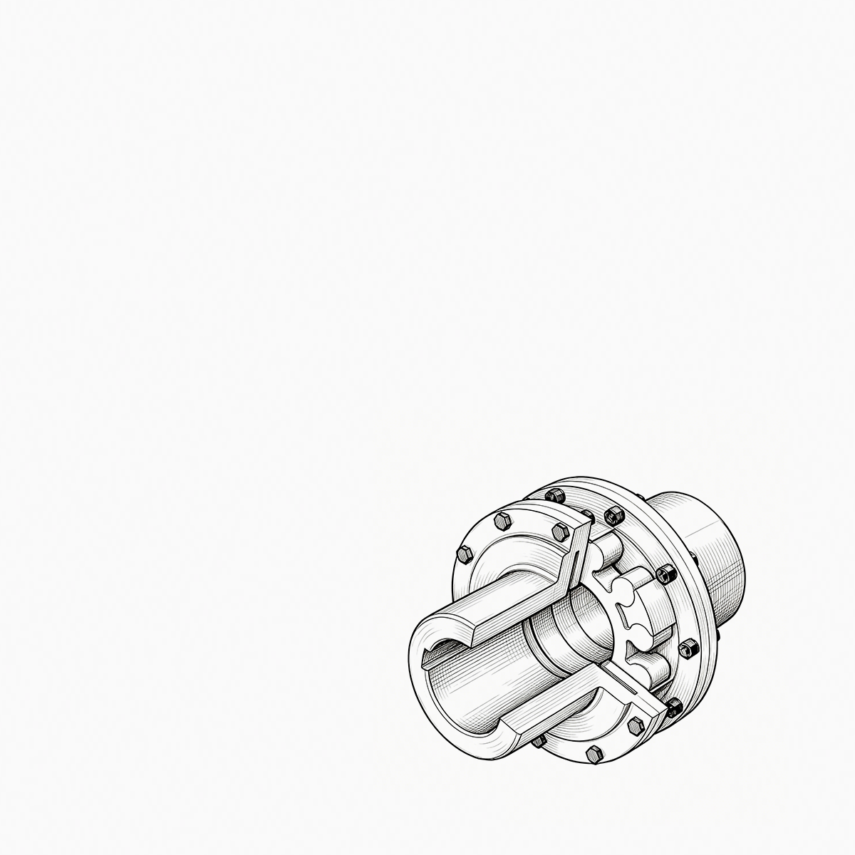
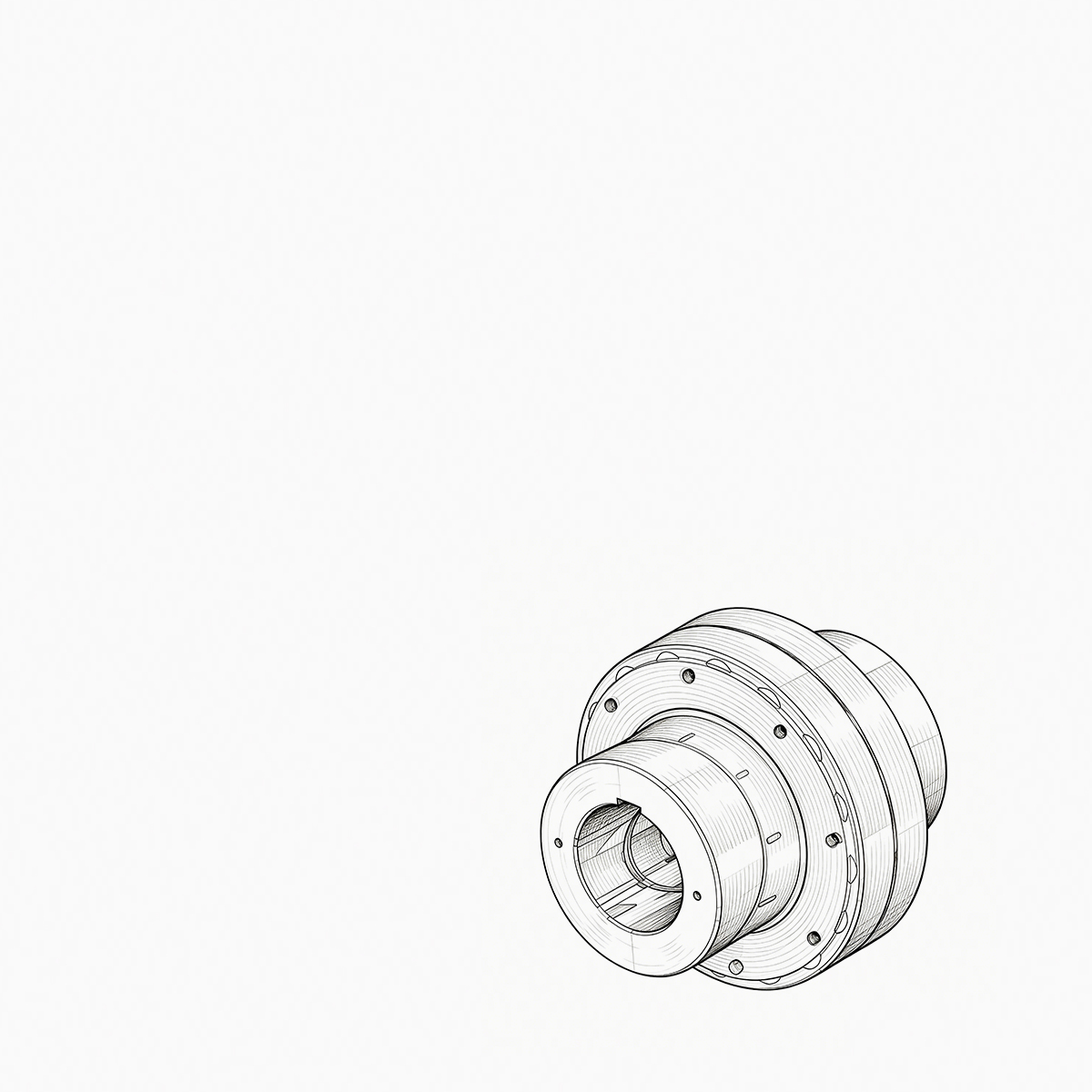
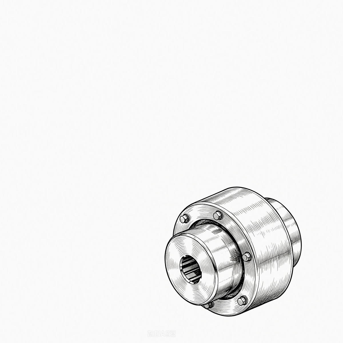
The main difference is that "gear coupling" is a broad category of flexible couplings using meshing gear teeth, while a "drum gear coupling" is one specific configuration within that category, featuring a single sleeve (drum) with internal teeth that meshes with external teeth on both connected shaft hubs. In practice, the term "gear coupling" more commonly refers to a double-engagement design with two separate sleeves connected by a center spool or bolted directly together, whereas the drum type uses one continuous outer sleeve spanning both hubs.
Both designs transmit torque through crowned gear teeth that allow limited relative motion between the internal and external teeth, which is what gives gear couplings their ability to accommodate shaft misalignment. The distinction matters because it directly affects installation length, misalignment capacity, maintenance access, and cost—factors that determine which design fits a given piece of rotating equipment.
How Each Coupling Type Is Constructed
Standard Gear Coupling Structure
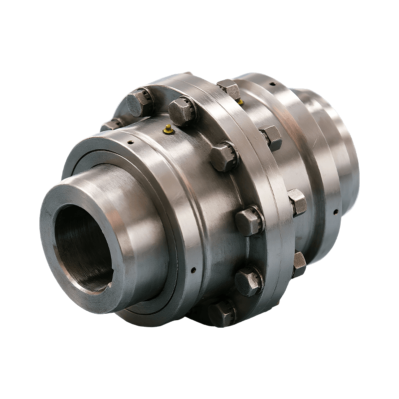
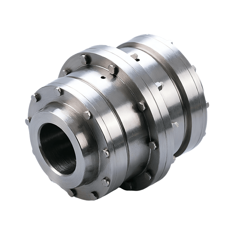
A standard gear coupling typically consists of two hubs, each with external gear teeth, mated to two internally toothed sleeves. The two sleeves are then joined by bolted flanges or a center spacer spool. This two-sleeve arrangement is sometimes called a "double engagement" coupling because each shaft has its own independent gear engagement point.
Drum Gear Coupling Structure
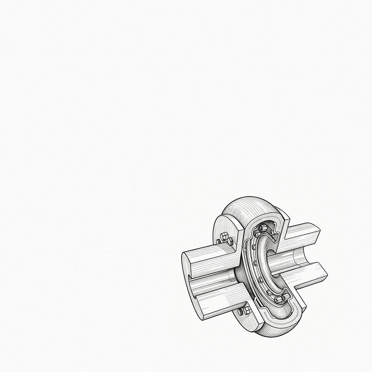
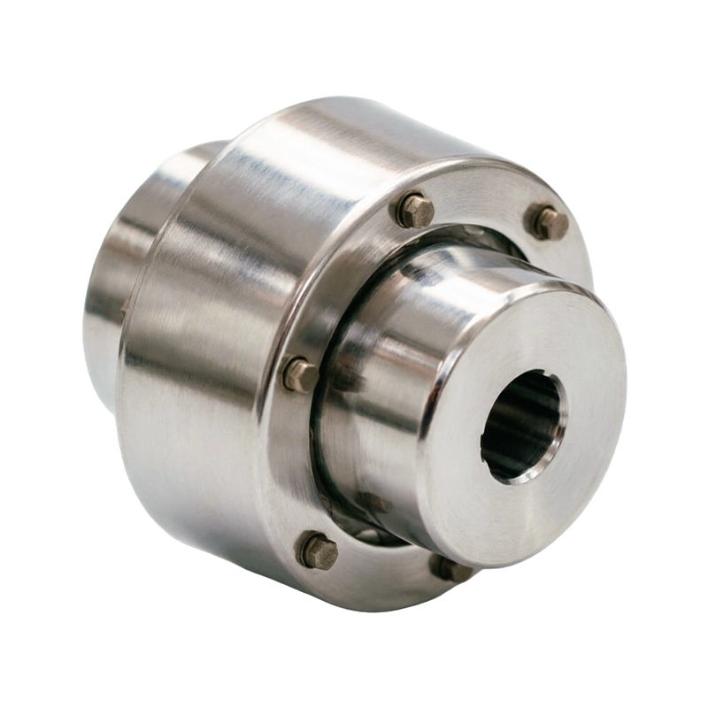
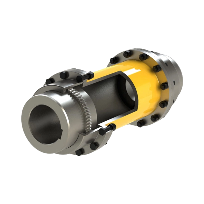
A drum gear coupling replaces the two separate sleeves with a single, continuous outer drum that has internal teeth cut along its entire length. This one-piece sleeve meshes with external teeth on both shaft hubs simultaneously, eliminating the center bolted joint found in standard designs. The drum shape gives the sleeve extra wall thickness and rigidity compared to a split-sleeve design of the same length.
| Feature | Standard Gear Coupling | Drum Gear Coupling |
|---|---|---|
| Sleeve design | Two separate sleeves | One continuous drum |
| Center joint | Bolted flange or spacer spool | None (single piece) |
| Overall length | Longer, especially with spacer | Shorter, more compact |
| Sleeve rigidity | Moderate | Higher due to thicker wall |
Misalignment Capacity and Torque Handling
Both coupling types rely on crowned teeth to accommodate misalignment, but the amount they can tolerate and the way they distribute load differs.
Standard Gear Coupling Misalignment
With two independent engagement points and often a spacer spool between them, standard gear couplings can accommodate larger parallel and angular offsets—typically up to 1.5 degrees of angular misalignment per mesh, or roughly 3 degrees combined across both engagements. The added spacer length also makes it easier to compensate for larger parallel misalignment between shafts.
Drum Gear Coupling Misalignment
Because the drum design uses a single mesh point, most drum gear couplings are rated for a smaller misalignment window, generally around 0.5 to 1 degree total. This makes them better suited to applications where shafts are already closely aligned and the coupling is mainly compensating for minor thermal growth or installation tolerance rather than large offset conditions.
In terms of torque capacity, both designs can be engineered for similar torque ranges when made from comparable materials, since torque capacity is primarily a function of tooth size, hardness, and pitch diameter rather than sleeve configuration. However, the thicker drum wall in a drum gear coupling can offer a slight advantage in torsional stiffness for a given outer diameter.
Installation, Space, and Maintenance Considerations
Because the drum gear coupling eliminates the center bolted connection, it typically requires 20–30% less axial installation length than a standard gear coupling with a spacer spool. This makes it a practical choice for equipment layouts where shaft-to-shaft distance is limited, such as compact pump skids or retrofit installations.
Standard gear couplings, on the other hand, offer easier maintenance access in some configurations. A spacer-type gear coupling can often be removed without disturbing the connected equipment, since the spacer spool can be unbolted and slid out independently. Drum gear couplings, being a single continuous piece, generally require axial movement of one of the connected machines to remove or service the coupling, which can increase downtime during maintenance.
- Confirm available shaft-to-shaft spacing before selecting coupling type.
- Check whether maintenance procedures require spacer removal without moving equipment.
- Verify expected misalignment based on foundation tolerances and thermal growth.
- Match torque rating to peak and continuous load conditions of the driven equipment.
Typical Applications for Each Coupling Type
Application requirements—particularly shaft spacing, expected misalignment, and space constraints—usually determine which coupling type is specified.
Where Standard Gear Couplings Are Used
- Large industrial pumps and compressors requiring a spacer for maintenance access
- Steel mill drives with significant shaft offset or thermal expansion
- Marine propulsion systems where larger misalignment tolerance is needed
- Power generation turbines with long shaft runs between components
Where Drum Gear Couplings Are Used
- Compact motor-to-gearbox connections with limited axial space
- Rolling mill drive lines where high torsional stiffness is prioritized
- Cement and mining equipment where shafts are precisely aligned during installation
- Retrofit projects replacing older couplings within a fixed footprint
Cost and Lifecycle Comparison
Drum gear couplings generally cost less to manufacture than standard gear couplings of equivalent torque rating, since they require fewer machined components and no separate bolted spacer assembly. Manufacturing savings of 10–15% are common for equivalent-capacity units, largely due to reduced part count and simpler assembly.
However, standard gear couplings can offer lower lifecycle costs in applications with frequent maintenance needs, because the modular spacer design allows technicians to service the coupling without disturbing shaft alignment on either connected machine. For equipment that rarely requires coupling removal, this advantage becomes less significant, and the drum gear coupling's lower upfront cost and smaller footprint often make it the more economical choice.
| Criteria | Standard Gear Coupling | Drum Gear Coupling |
|---|---|---|
| Misalignment tolerance | Higher (up to ~3°) | Lower (~0.5–1°) |
| Axial footprint | Larger | Smaller (20–30% less) |
| Maintenance access | Easier (removable spacer) | Requires axial shift to service |
| Manufacturing cost | Higher | Lower (10–15% less) |
How to Choose Between the Two
The right coupling depends on three practical factors: available installation space, expected misalignment, and maintenance strategy. If shaft spacing is tight and alignment is already well controlled, a drum gear coupling is usually the more efficient and cost-effective choice. If the application involves larger shafts, significant thermal growth, or a maintenance program that benefits from removing a coupling without disturbing connected machinery, a standard gear coupling with a spacer is typically the better fit.
Engineers should also confirm torque and speed ratings against the specific equipment's operating conditions, since both coupling types are available across a wide range of sizes and material grades. Consulting the coupling manufacturer's rating charts for the specific bore size, torque, and RPM combination ensures the selected coupling—whether standard or drum type—matches the actual demands of the drive system rather than relying on general category assumptions alone.
PREV: What Are the Critical Factors for Selecting the Right Industrial CouplingsNEXT: China's Coupling Market Exceeds 48 Billion Yuan in 2026, Intelligence and Greenization Drive High-Quality Industry Transformation
Be the First to Know
For exclusive deals and latest offers, sign up by entering your email address below.
Related products
News
-
-
Consider a 250 kW crane hoist that begins to vibrate only when the load is lifted. The drum gear coupling is inspected ...
READ MORE -
China's coupling industry is at a critical historical juncture of transformation from scale expansion to quality and eff...
READ MORE -
Industrial Couplings: The Definitive Technical Encyclopedia – Classification, Sizing, Failure Prevention, and Lifecycle...
READ MORE -
During a routine vibration survey on a high-speed compressor train, engineers found a 4.5 mm/s velocity spike at the mo...
READ MORE -
Your compressor train is running at 9,800 rpm when the vibration monitor triggers an alarm. The first component your ma...
READ MORE


ABOUT US
PRODUCTS
INDUSTRIES
CONTACT US
- Phone: +86-18652865511
- Email: sales@ohmach.com
- Address: No.1, Minying Developing Zone, Zhenjiang, Jiangsu, China
Copyright Zhenjiang Orienthold Machinery Co., Ltd. All Rights Reserved.
 Custom Industrial Shaft Coupling Manufacturers