 English
 русский
 Português
 عربى
عربى
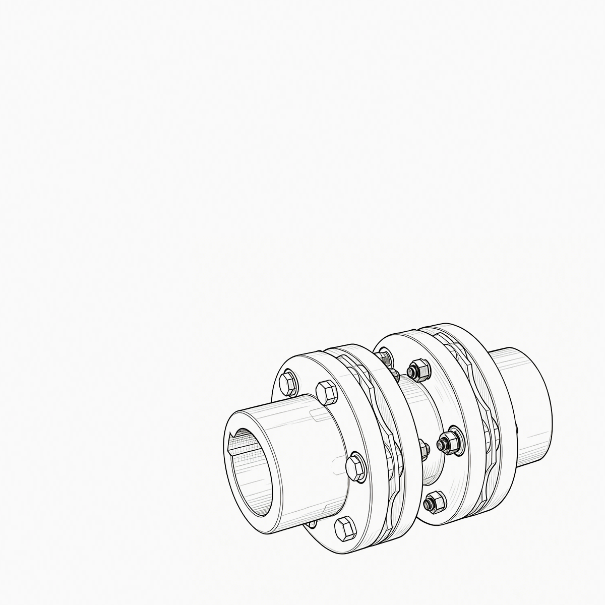
Rotating Equipment Engineering Why Diaphragm Coupling Wins in High-Speed Turbomachinery A close look at how elastic dia...
READ MORE
What Are the Critical Factors for Selecting the Right Industrial Couplings
Admin 2026-08-19Content
- 1 Industrial Couplings: The Definitive Technical Encyclopedia – Classification, Sizing, Failure Prevention, and Lifecycle Management
- 1.1 1. The Two Broad Categories of Industrial Couplings and Their Mechanical Essence
- 1.2 2. Comprehensive Performance Comparison of Ten Common Industrial Coupling Types (Engineering Selection Matrix)
- 1.3 3. The Four Core Engineering Missions of Industrial Couplings
- 1.4 4. Engineering Terminology: Coupling vs. Coupler – A Critical Distinction
- 1.5 5. Six‑Step Selection Procedure with Worked Example and Comparative Chart
- 1.6 6. Critical Materials and Advanced Manufacturing Processes for Industrial Couplings
- 1.7 7. Installation Alignment Standards and Maintenance Schedules
- 1.8 8. Field Failure Modes – Diagnosis and Remediation
- 1.9 9. The Systemic Indispensability of Industrial Couplings in Modern Drive Trains
- 1.10 10. Key Performance Metrics and Advanced Features of Industrial Couplings
Industrial Couplings: The Definitive Technical Encyclopedia – Classification, Sizing, Failure Prevention, and Lifecycle Management
industrial couplings are the precision mechanical interfaces that underpin virtually every rotating machinery system in heavy industry. From multi‑megawatt wind turbine drivetrains to high‑speed CNC spindles, industrial couplings perform the critical duties of torque transmission, geometric misalignment accommodation, torsional vibration damping, and overload disconnection. This article draws upon mechanical design principles, materials science, and field failure analysis to deliver a systematic exposition of industrial couplings – their technical classifications, quantitative sizing methodologies, installation and maintenance standards, and common failure modes. It is intended as an on‑the‑job engineering reference for drive system designers, reliability engineers, and procurement specialists.
1. The Two Broad Categories of Industrial Couplings and Their Mechanical Essence
Rigid Couplings – Zero‑displacement Constraint Systems
Rigid couplings permit no relative motion whatsoever between the driving and driven shafts. They rely on high‑precision machined surfaces (e.g., finely turned diameters and ground end faces) and precisely fitted keys or taper pins to achieve a fixed connection. Their torsional stiffness is theoretically infinite, introducing zero backlash – making them ideal for applications that demand absolute synchronisation, such as printing register mechanisms or jig boring machine indexing drives. Typical rigid types include sleeve couplings (with interference or taper bushings), flange couplings (using reamed bolts for torque transfer), and clamp couplings (which transmit torque through radial friction). However, the Achilles’ heel of rigid industrial couplings is their extreme sensitivity to installation misalignment: once the coaxiality error exceeds 0.02 mm, the resulting additional bending moments overload the bearings, causing overheating and, in severe cases, fatigue fracture of the main shaft. Hence, shafts equipped with rigid couplings demand laser alignment both cold and hot, with regular monitoring of foundation settlement.
Flexible Couplings – Elastic Compensation Systems
Flexible couplings incorporate elastic elements (metallic diaphragms, bellows, serpentine springs, or rubber/polyurethane components) or geometric compensating structures (tooth clearance in gear couplings) to actively absorb radial, axial, and angular shaft displacements. Their mechanical behaviour can be modelled as a spring‑damper system with defined stiffness and damping coefficients. Flexible couplings not only drastically reduce additional bearing loads caused by misalignment, but also effectively isolate torque fluctuations from prime movers (engines or electric motors), protecting downstream sensitive equipment. Based on the elastic material, they are subdivided into metallic flexible types (disc, diaphragm, gear, and grid) and elastomeric types (jaw, tyre, and pin‑bush). Metallic flexible couplings offer wide temperature tolerance (-50°C to +280°C) and high load capacity, but gear and grid designs require periodic lubrication; elastomeric types are simple, maintenance‑free, and exhibit high damping ratios (0.08–0.20), yet their temperature and oil resistance are constrained by the polymer properties, making them more suitable for general‑duty pumps, fans, and compressors. Industry data indicate that, under identical operating conditions, selecting an appropriate flexible industrial couplings can extend the L10 bearing life by 35% to 70% – representing the most cost‑effective reliability upgrade for any drive train.
2. Comprehensive Performance Comparison of Ten Common Industrial Coupling Types (Engineering Selection Matrix)
| Type | Radial (mm) | Axial (mm) | Angular (°) | Damping Ratio | Lubrication | Max Speed (rpm) |
| Sleeve (Rigid) | 0 | 0 | 0 | ≈0 | None | ≤3,000 |
| Flange (Rigid) | 0 | 0 | 0 | ≈0 | None | ≤2,500 |
| Gear (Flexible) | ±0.6 | ±3.5 | ±1.5 | 0.03–0.05 | Grease | ≤6,000 |
| Disc (Flexible) | ±0.4 | ±2.5 | ±1.0 | 0.04–0.08 | None | ≤15,000 |
| Bellows (Flexible) | ±0.3 | ±2.0 | ±1.5 | 0.05–0.10 | None | ≤30,000 |
| Jaw (Elastomeric) | ±0.6 | ±3.5 | ±2.0 | 0.10–0.20 | None | ≤8,000 |
| Tyre (Elastomeric) | ±1.0 | ±4.0 | ±2.5 | 0.15–0.25 | None | ≤5,000 |
| Grid (Flexible) | ±0.8 | ±3.0 | ±1.8 | 0.12–0.18 | Grease | ≤7,000 |
Note: Tolerance values are typical for standard sizes; consult individual datasheets for exact figures.
3. The Four Core Engineering Missions of Industrial Couplings
Mission 1: Efficient High‑Torque, High‑Power Transmission
The primary duty of industrial couplings is to transfer mechanical torque from the prime mover (electric motor, diesel engine, or steam turbine) to the driven machine (pump, compressor, fan, or rolling mill) with minimal loss. During operation, the coupling must withstand both steady‑state loads and transient torque spikes. For instance, in a steel roughing mill, peak torques can reach 4–6 times the nominal value – gear or grid type industrial couplings, with their high yield strength and impact resistance, ensure uninterrupted power flow. Transmission efficiency directly affects energy consumption; rigid couplings can achieve >99.9% efficiency, while flexible types, due to internal damping and friction, range from 98% to 99.5%, which can be optimised through tooth profile or diaphragm thickness design.
Mission 2: Multi‑Dimensional Misalignment Compensation
Absolute alignment is unattainable in real‑world engineering. Foundation settlement, pipe strain, thermal expansion, and bearing wear all introduce radial, axial, and angular offsets between shafts. Without compensation, these displacements generate destructive constraint forces that overload bearings. Flexible industrial couplings absorb these movements through elastic deformation or relative sliding. For example, a disc coupling’s metallic diaphragm pack flexes under axial tension/compression to allow ±2.5 mm axial float, while its convoluted shape accommodates ±0.4 mm radial error. This capability protects bearings and prevents bending fatigue of the main shaft – a critical factor in extending the entire drive train’s service life.
Mission 3: Torsional Vibration and Shock Load Damping
Internal combustion engine firing pulses, electric motor harmonic torques, and impact loads from crushers all excite torsional oscillations in the driveline. If unchecked, these oscillations cause gear tooth pitting, spline wear, or even shaft fracture. High‑damping industrial couplings (elastomeric and grid types) convert shock energy into heat through internal friction. The loss factor of rubber or polyurethane elements can reach 0.10–0.25, effectively reducing dynamic amplification factors. For applications with frequent start‑stop or reversing cycles (e.g., crane hoists), selecting a high‑damping coupling significantly smooths operation and reduces peak stresses.
Mission 4: Overload Safety Disconnection
Certain industrial couplings integrate torque‑limiting features, acting as the weak link in the drive chain. When the driven machine jams or stalls, causing torque to exceed a preset threshold, shear pins break or ball‑detent mechanisms disengage, instantaneously interrupting power transmission. This safety function protects expensive motors and gearboxes from catastrophic damage. Shear‑pin couplings offer trip accuracy of ±5% of set torque with millisecond response times, and are widely used in screw conveyors, bucket elevators, and agitators – a low‑cost yet highly reliable protection strategy.
4. Engineering Terminology: Coupling vs. Coupler – A Critical Distinction
Coupling
In mechanical power transmission, a coupling is a precision component dedicated to connecting two rotating shafts for the purpose of torque and motion transfer. It conforms to established interface standards (cylindrical or tapered shafts, parallel or involute splines) and its performance parameters (rated torque, fatigue strength, moment of inertia, critical speed) are rigorously calculated. The connection may be permanent (shrink‑fit rigid couplings) or detachable (flanged types). The term is precisely defined in international standards such as ISO 14691 and AGMA 9000.
Coupler
Coupler is a broader, cross‑disciplinary term. In fluid power it denotes quick‑release hydraulic connectors; in electronics it refers to optical or RF couplers; even within mechanical engineering, coupler may refer to quick‑connect devices or non‑torque‑transmitting linkages (e.g., drawbar couplers). Thus, using “coupler” in a procurement or design document risks ambiguity. For rotary shaft power transmission, the correct and unambiguous term is coupling – which is why all authoritative product catalogues classify these devices under “Industrial Couplings”.
5. Six‑Step Selection Procedure with Worked Example and Comparative Chart
Correct selection of industrial couplings is the cornerstone of long‑term reliability. The industry‑standard procedure comprises six steps, illustrated here with a complete numerical example.
- Step 1: Determine driver power and speed (Pm, nm) from motor nameplate or driven machine requirement.
- Step 2: Calculate nominal torque TN = 9550 × P / n (N·m).
- Step 3: Establish service factor K based on load type (uniform, moderate shock, heavy shock) and daily operating hours (typically 1.0–2.5).
- Step 4: Compute corrected torque TD = TN × K. The selected coupling’s rated torque TR ≥ TD.
- Step 5: Verify bore and keyway dimensions against shaft diameters and key standards (GB/T 1095 or ANSI B17.1).
- Step 6: Check critical speed – for high‑speed applications, ensure the coupling’s lateral critical speed is at least 15% away from the operating range.
Worked Example:
A centrifugal pump is driven by a 160 kW motor at 1480 rpm. Load is moderate shock (K=1.75), ambient temperature 40°C (elastomeric couplings require a temperature correction of 0.95).
TN = 9550 × 160 / 1480 ≈ 1032 N·m
TD = 1032 × 1.75 / 0.95 ≈ 1901 N·m
Therefore, select an elastomeric industrial couplings with rated torque ≥1901 N·m, and verify that the shaft diameter (φ65 mm, key width 18 mm) is within the coupling’s bore range.
Typical Service Factors K
- Uniform load (fans, light conveyors): 1.0–1.2
- Moderate shock (centrifugal pumps, compressors): 1.3–1.7
- Heavy shock (crushers, rolling mills): 1.8–2.5
- Frequent reversals (cranes, winches): 2.0–3.0
Temperature derating: for elastomeric types, reduce rating by 0.5% per °C above 80°C; metallic types require no correction.
Qualitative Comparison of Torque Density and Misalignment Capacity across Coupling Types
Gear
Disc
Jaw
Grid
Bellows
Torque density (high → low) vs Misalignment capability (low → high)
Qualitative representation – consult manufacturer data for precise values
6. Critical Materials and Advanced Manufacturing Processes for Industrial Couplings
Alloy Structural Steels
Grades such as 40Cr, 42CrMo, and 34CrNiMo6 are quenched and tempered to achieve a fine balance of strength and toughness (UTS 900–1100 MPa). They are widely used for gear coupling rings and flanges, resisting contact fatigue and tooth bending.
Stainless and Heat‑Resistant Steels
For offshore, chemical, and food applications, 304 or 316L stainless steel provides excellent corrosion resistance. For high‑temperature turbine couplings, precipitation‑hardening grades like 17‑4PH maintain yield strength up to 450°C.
High‑Performance Elastomers
Jaw coupling spiders are typically moulded from polyurethane (PU) or nitrile rubber (NBR). PU offers excellent abrasion and tear resistance (80–95 Shore A), while NBR is oil‑resistant, making it ideal for hydraulic pump drives. Injection or compression moulding controls the damping properties.
Surface Hardening Treatments
Carburising and quenching gear teeth to 58–62 HRC enhances scuffing resistance while retaining a tough core. Phosphate or MoS₂ coatings reduce friction during break‑in, especially for industrial couplings operating under boundary lubrication.
7. Installation Alignment Standards and Maintenance Schedules
Precision Alignment Requirements
Using laser alignment tools, for general‑purpose equipment below 3000 rpm, radial misalignment should be ≤0.05 mm and angular ≤0.05 mm/100 mm. For high‑speed turbomachinery (>10,000 rpm), these values tighten to 0.02 mm and 0.02 mm/100 mm. Every 0.1 mm increase in misalignment can raise bearing loads by 15–20%. For hot‑running trains (e.g., steam turbines), cold‑set pre‑offsets must be calculated to accommodate thermal growth, ensuring correct alignment at operating temperature.
Lubrication and Periodic Maintenance
For grease‑lubricated gear and grid couplings, use EP (extreme pressure) lithium‑based grease (NLGI #2). Fill to 70–80% of cavity volume – overfilling causes churning heat. Under normal conditions, re‑lubricate every 2,000 hours or 3 months; at elevated temperatures (>80°C) or high humidity, shorten to monthly intervals. Every six months, re‑torque bolted joints with a calibrated wrench to prevent loosening. For elastomeric types, inspect the insert quarterly for cracking, swelling, or hardness change >5 Shore A – replace if detected.
8. Field Failure Modes – Diagnosis and Remediation
Failure: Gear coupling tooth wear and pitting
Root cause: Lubricant starvation or degradation, combined with angular misalignment exceeding 1.5°, leads to edge loading and contact stress above the endurance limit (σH). Remedy: Switch to synthetic EP grease, re‑align to ≤1.0°, and verify tooth hardness meets design specification.
Failure: Disc coupling diaphragm fracture
Root cause: High‑cycle fatigue from resonant operation (speed near critical) or excessive axial pre‑load (>±3 mm). Remedy: Conduct torsional vibration analysis, adjust operating speed or select a stiffer diaphragm pack; reset axial spacing at cold condition with correct thermal allowance.
Failure: Jaw spider overheating and melting
Root cause: Polyurethane softens above 120°C due to repeated overload, poor ventilation, or chemical attack from oil. Remedy: Upgrade to Hytrel® (150°C capability), add cooling slots in the guard, or switch to NBR if oil mist is present.
9. The Systemic Indispensability of Industrial Couplings in Modern Drive Trains
From a system dynamics standpoint, industrial couplings are far more than mere connectors – they act as the “mechanical fuse” and “dynamic filter” of the rotating machinery system. Their irreplaceability stems from three dimensions:
- Decoupling: They allow the motor and driven machine to be independently located, providing design freedom for layout, installation, and maintenance – impossible with rigid‑integrated designs.
- Economic efficiency: By centralising misalignment compensation and vibration absorption at the coupling, bearing, seal, and gear manufacturing tolerances can be relaxed, achieving the same system life at lower cost. Data shows that, for identical life targets, systems fitted with high‑quality flexible couplings can reduce total manufacturing expense by 12–18%.
- Safety: Overload‑protected industrial couplings are the last line of defence against catastrophic equipment damage. In mining crushers, if a tramp metal event or stall occurs without timely disconnection, motor rotor failure or gearbox casing rupture can lead to enormous financial loss and safety hazards.
Consequently, industrial couplings represent an optimal solution validated by centuries of industrial practice, and their technical value is codified in every major mechanical design handbook and engineering standard.
>75%
of industrial drive failures are linked to improper coupling selection or maintenance
Correct selection can boost system MTBF by 2–3×
10. Key Performance Metrics and Advanced Features of Industrial Couplings
500 kN·m
Maximum single‑unit torque capacity (heavy‑duty gear type)
±0.5°~±3°
Angular misalignment capability range (elastomeric and metallic types)
30,000 rpm
Maximum permissible speed for precision bellows couplings
-50°C~+280°C
Wide temperature range for all‑metallic flexible couplings
<0.01°
Torsional backlash – near‑zero for precision disc couplings, ideal for servo control
These performance ranges cover everything from micro‑precision drives to heavy‑duty mining applications. For application‑specific customised industrial couplings solutions, further rotor dynamics analysis and FEA validation can be performed.
Engineering Takeaway: A Holistic View from Selection to Field Service
Selecting industrial couplings is not a mere table‑lookup exercise – it demands a systems‑level analysis covering load spectrum, installation space, environmental compatibility, and life‑cycle cost. Engineers should define the drive’s dynamic characteristics (starting torque, braking torque, shock frequency) early, and build in sufficient margin for misalignment and thermal growth. In the field, a predictive maintenance regime based on vibration monitoring and lubricant analysis minimises unplanned downtime. Remember: a well‑chosen industrial couplings should last as long as the major overhaul interval of the equipment it connects – that is the ultimate measure of selection success.
For detailed installation drawings, finite element analysis reports, or torsional vibration case studies, stay tuned to our technical channel, or contact our engineering team directly regarding your industrial couplings requirements.
PREV: What makes a diaphragm coupling more suitable than a gear coupling for high-speed turbomachinery applications?NEXT: Gear Coupling vs. Drum Gear Coupling: Key Differences Explained
Be the First to Know
For exclusive deals and latest offers, sign up by entering your email address below.
Related products
News
-
-
Your compressor train is running at 9,800 rpm when the vibration monitor triggers an alarm. The first component your ma...
READ MORE -
A rotating equipment engineer at a steel finishing mill recently described a flexible coupling that had failed twice in...
READ MORE -
A maintenance engineer pulls a failed coupling from a pump drive. The elastomer sleeves are cracked, the pin bolts are ...
READ MORE -
China's coupling industry is at a critical historical juncture of transformation from scale expansion to quality and eff...
READ MORE -
During a routine vibration survey on a high-speed compressor train, engineers found a 4.5 mm/s velocity spike at the mo...
READ MORE


ABOUT US
PRODUCTS
INDUSTRIES
CONTACT US
- Phone: +86-18652865511
- Email: sales@ohmach.com
- Address: No.1, Minying Developing Zone, Zhenjiang, Jiangsu, China
Copyright Zhenjiang Orienthold Machinery Co., Ltd. All Rights Reserved.
 Custom Industrial Shaft Coupling Manufacturers