 English
 русский
 Português
 عربى
عربى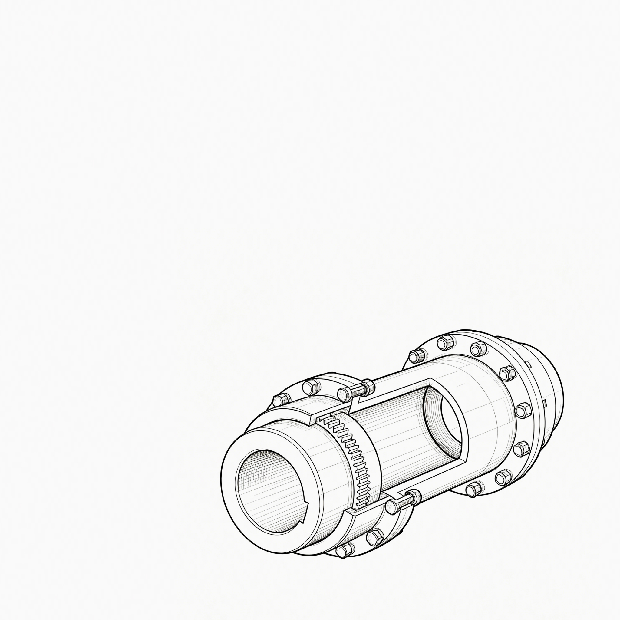
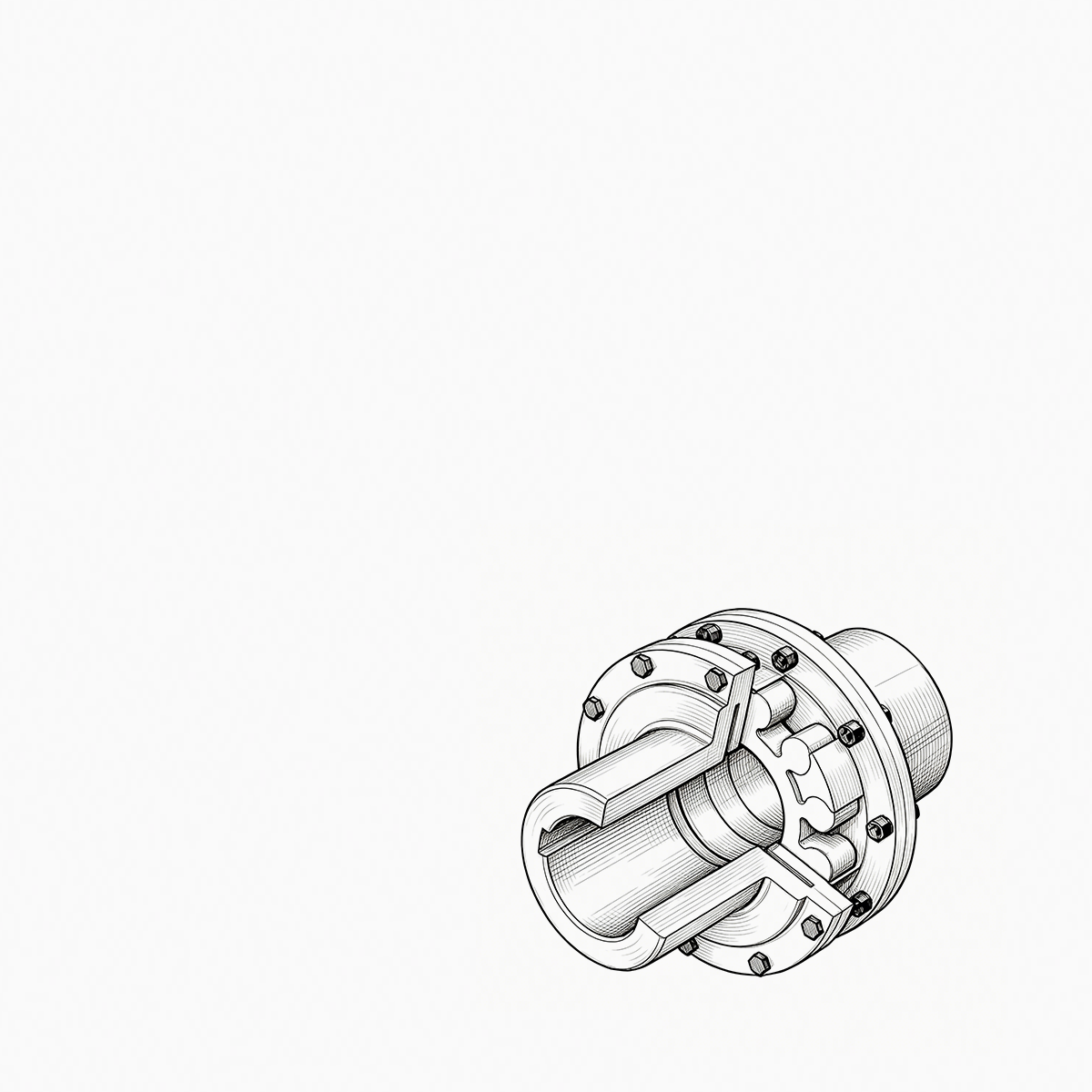
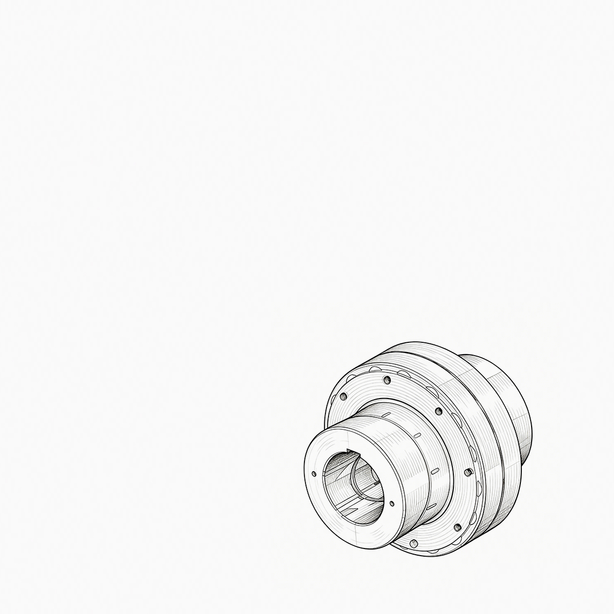
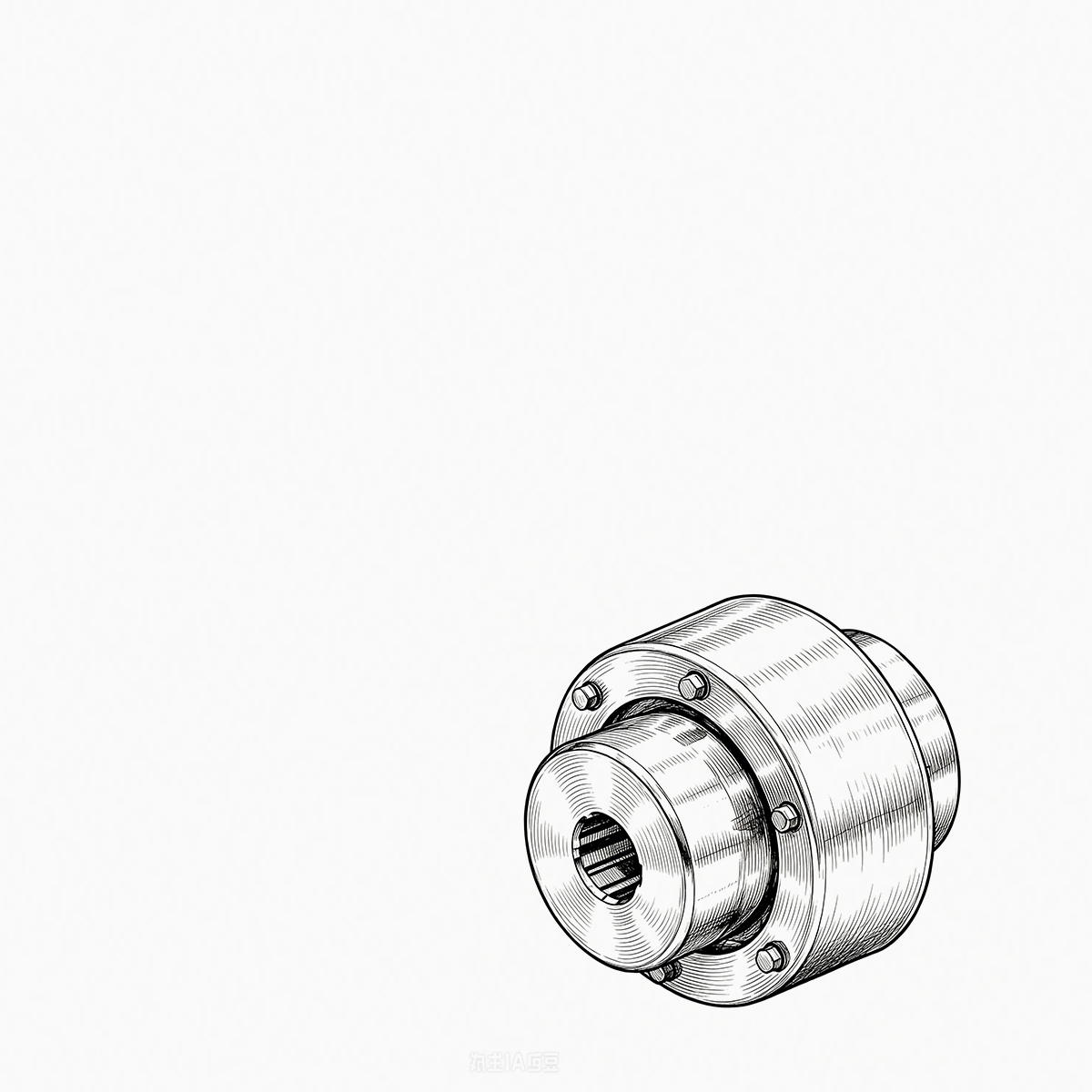
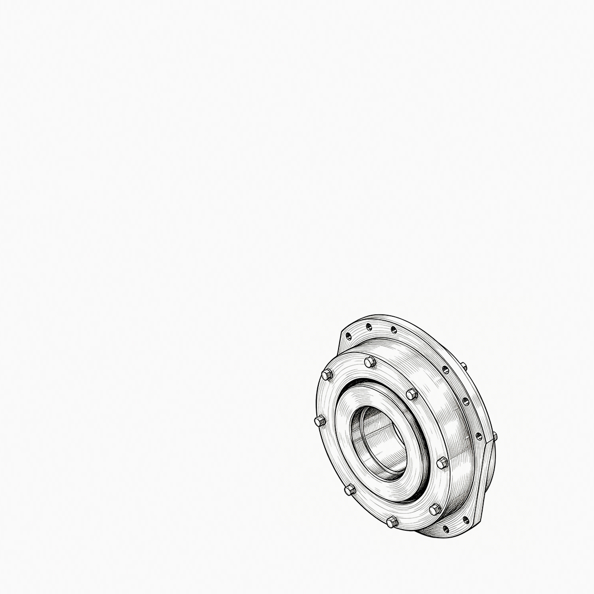
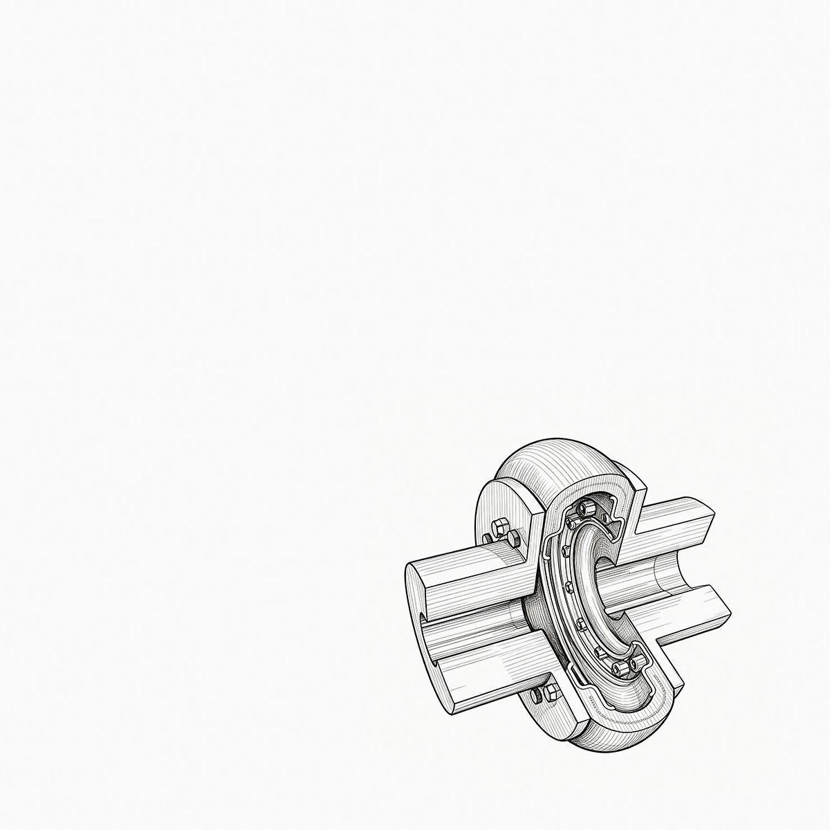
Two quotes land for the same replacement gear coupling: $1,850 from one shop and $2,600 from another. Both promise standard compliance, both quote four weeks, and the drawings look identical. The 40% gap almost never sits in the steel price. It sits in tooth geometry and heat treatment, hub bore an...
READ MORE
 Product Category
Cross Universal Coupling Manufacturers
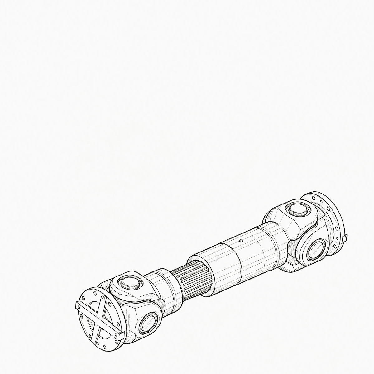
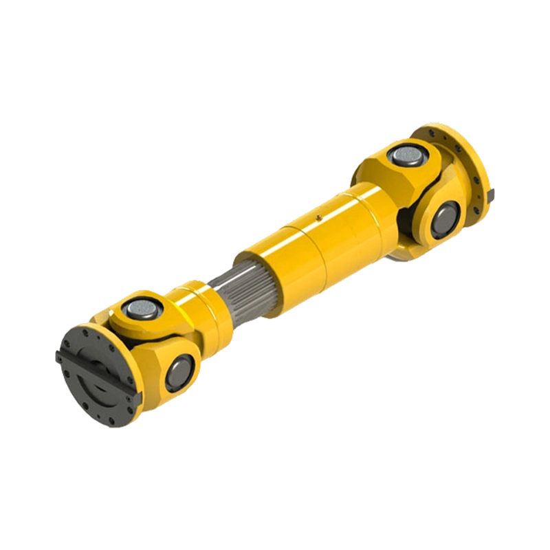
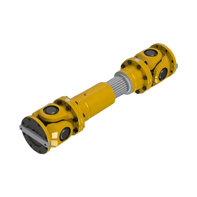
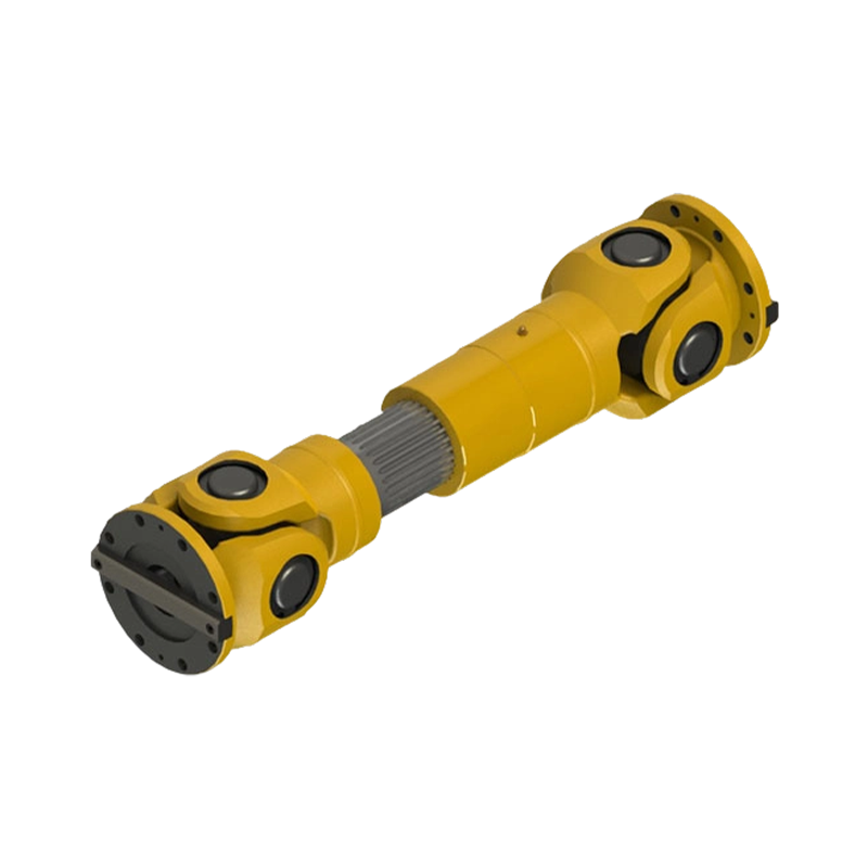
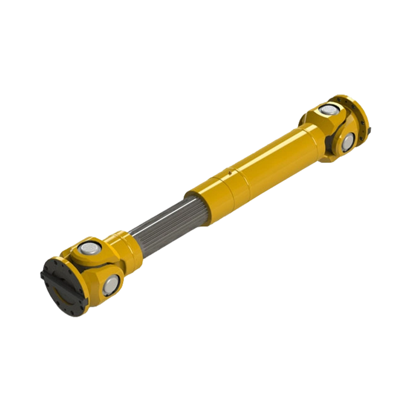
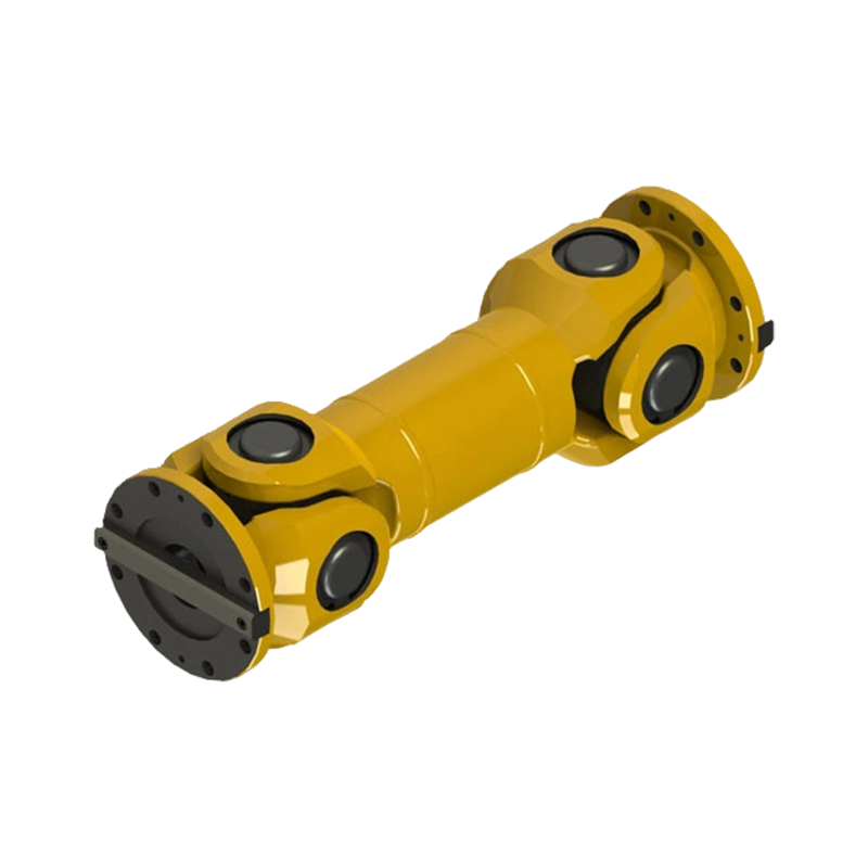
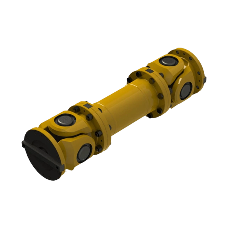
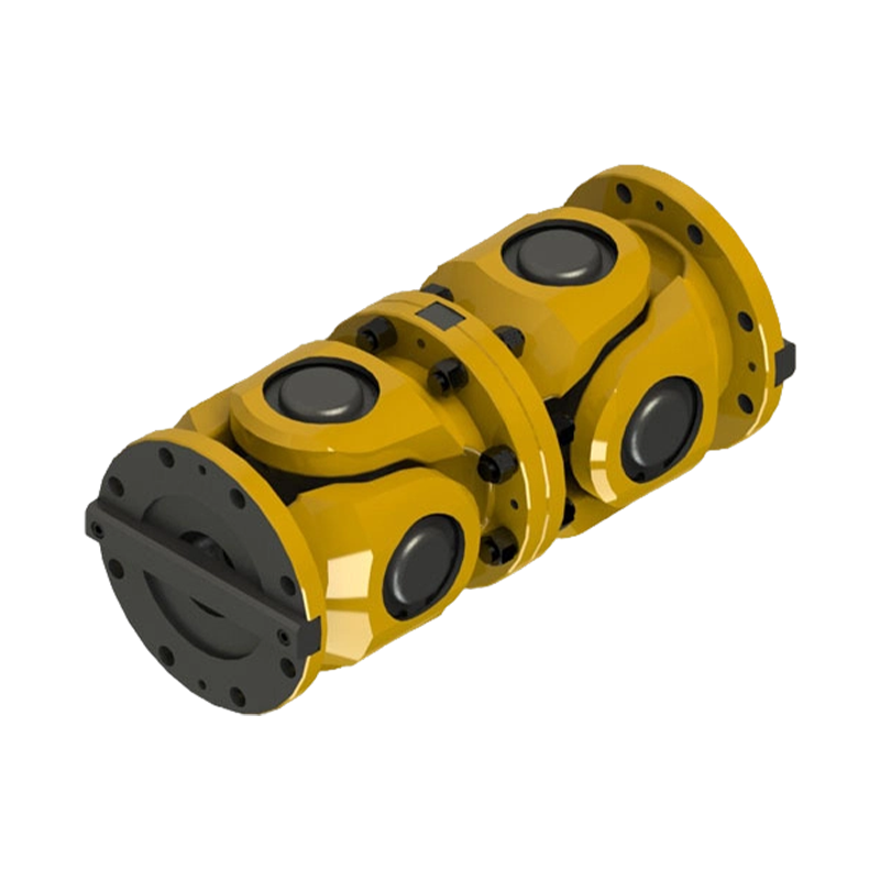
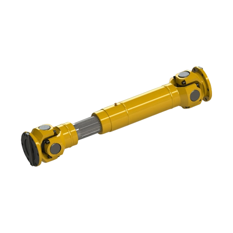
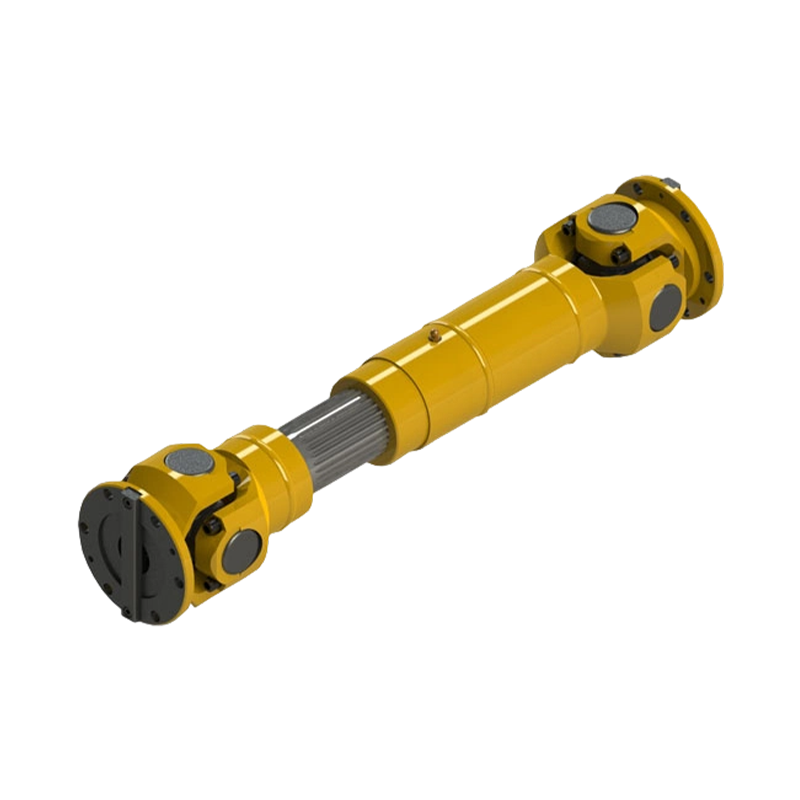
A cross universal coupling is a key connecting component widely used in industrial transmission systems, primarily designed to transmit power between two shafts that operate at an angle or whose axes are not collinear. Compared with conventional rigid or flexible couplings, cross universal couplings offer clear advantages in angular compensation, enabling stable torque transmission under complex operating conditions. As a result, they have been extensively applied in industries such as metallurgy, mining, construction machinery, papermaking, port handling, and heavy equipment manufacturing. In particular, in applications where equipment layout is restricted, shaft systems are subject to significant thermal deformation, or dynamic misalignment occurs during operation, cross universal couplings often play a critical role in ensuring the reliable operation of the entire transmission system.
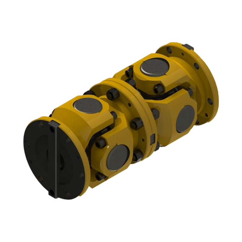
From a structural and functional perspective, a cross universal coupling achieves continuous rotation and torque transmission within a certain angular range through the coordinated interaction of the cross shaft, universal joint yokes, and needle roller bearings. This configuration effectively absorbs shaft misalignment caused by installation errors and operational vibration, while also mitigating the impact of thermal expansion and load fluctuations on the transmission system. As a result, equipment can maintain stable and smooth operation even under heavy loads and variable working conditions.
In practical engineering applications, cross universal couplings have developed into a relatively mature range of models to meet diverse requirements for load capacity, axial compensation, and structural dimensions. The commonly used SWC and SWP series each emphasize different design concepts: the former focuses on high structural rigidity and superior torque-carrying capacity, making it suitable for heavy-duty equipment operating continuously over long periods; the latter places greater emphasis on ease of maintenance and on-site disassembly efficiency, making it well suited for production environments where maintenance cycles and downtime must be minimized. Through various combinations of shaft diameters, center distances, and telescopic travel, cross universal couplings can be flexibly adapted to a wide range of industrial equipment layouts.
Company

Zhenjiang Orienthold Machinery Co., Ltd.
Zhenjiang Orienthold Machinery Co., Ltd. is China SWC/SWP Type Universal Coupling Manufacturers and OEM/ODM Telescopic Universal Coupling Suppliers, We are a medium-sized enterprise specialized in the production of couplings and papermak-ing machinery, integrating design, production and service.
Boasting strong technical strength, advanced equipment and comprehensive testing methods, our products are widely used in industries and equipment such as transportation, metallurgy, chemical engineering, mining, construction and hoisting, and are supplied to various large-scale enterprises all year round.
Equipped with a strict quality supervision system as well as complete inspection and testing instruments and equipment, our products fully comply with national standards. In particular, the production technology and quality of our papermaking machinery have reached international levels. Our products have won wide praise in the market and gained high recognition from customers.
News
-
-
Consider a 250 kW crane hoist that begins to vibrate only when the load is lifted. The drum gear coupling is inspected after a few months and the tooth wear is concentrated on one flank. The common diagnosis is not a single defective component; it is a mismatch between the catalogue torque, the act...
READ MORE -
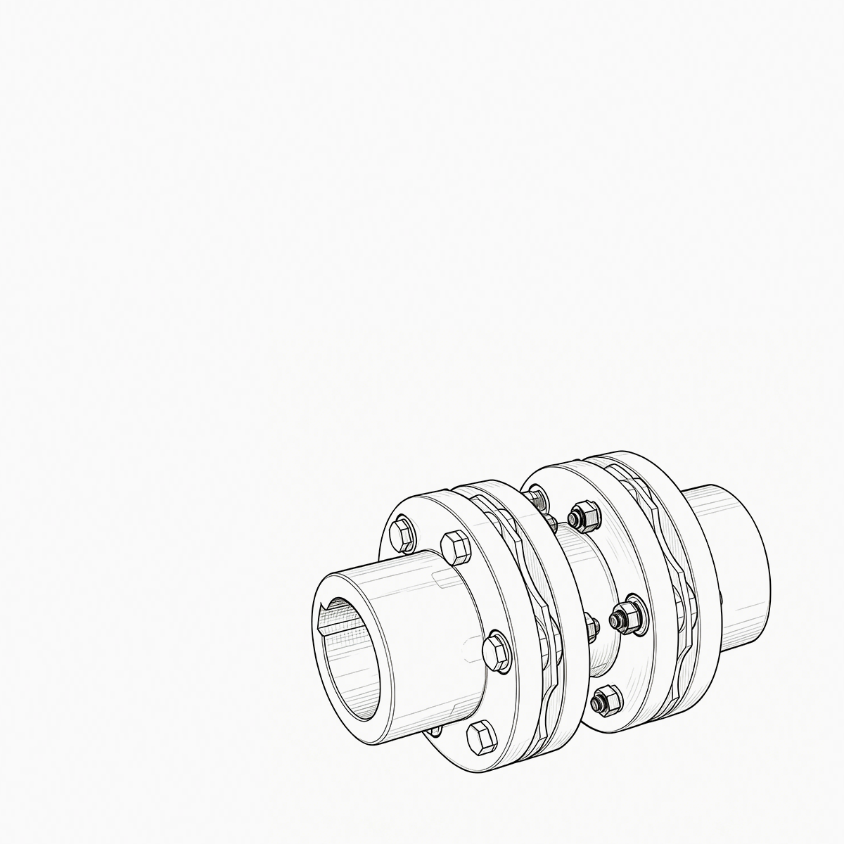
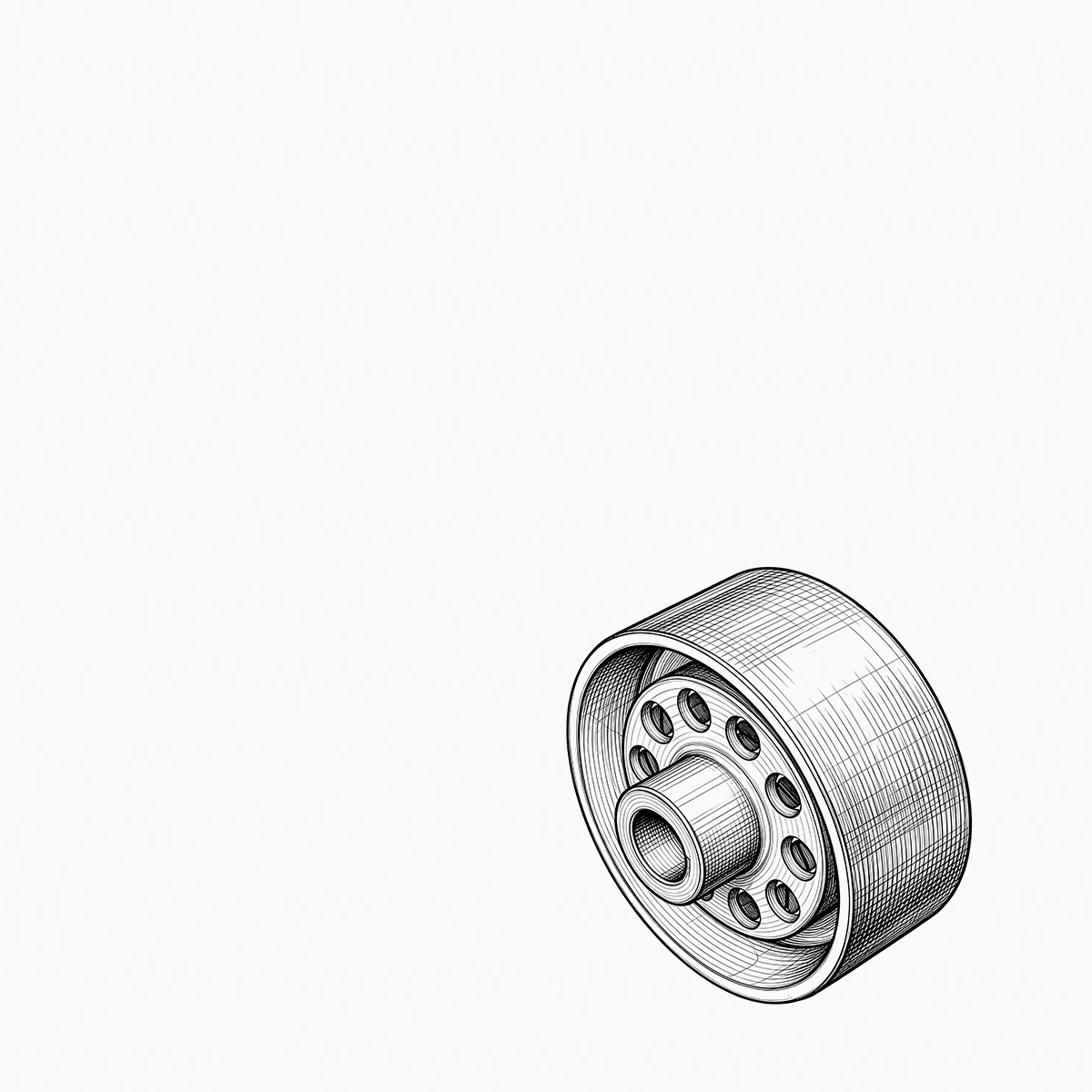
A maintenance engineer pulls a failed coupling from a pump drive. The elastomer sleeves are cracked, the pin bolts are scored, and the hub bore shows the tell-tale fretting marks of a poor fit. For most medium-duty industrial drives, the replacement is not an exotic engineering exercise: an elastic...
READ MORE
Message Feedback
Cross Universal Coupling Industry knowledge
Selection Criteria for Cross Universal Couplings in High-Speed Industrial Equipment
Rotational Speed Boundaries and Dynamic Balancing Standards
Selecting a cross universal coupling for high-speed equipment requires thorough evaluation of rotational speed limits and centrifugal force effects. As rotational velocity increases, any minor eccentricity or unbalance in the cross spider, yoke arms, or connecting flange generates centrifugal forces proportional to the square of the rotational speed. Zhenjiang Orienthold Machinery Co., Ltd. incorporates precise dynamic balancing procedures into the manufacturing of couplings used in high-speed applications across transportation, paper machinery, and chemical engineering. At elevated speeds, unbalanced mass causes radial shaft oscillations, bearing fatigue, and structural vibration in driving and driven machinery.
To prevent mechanical resonance and vibration, cross universal couplings operating at elevated speeds must be dynamically balanced according to established standards such as ISO 1940. The balancing procedure involves two-plane dynamic balancing of the complete assembly, including the cross spider bearings, flanged hubs, and intermediate shaft. Lower-speed applications tolerate higher residual unbalance levels, whereas high-speed equipment requires balance quality grades such as G2.5 or G6.3. The table below illustrates standard balance quality recommendations across operational speed ranges.
| Operational Speed Range (RPM) | Recommended ISO Balance Quality Grade | Typical Industrial Application | Permissible Residual Unbalance Level |
| Below 1000 RPM | G 16 | Heavy Mining Conveyors and Crane Hoists | Higher residual tolerance allowable |
| 1000 RPM to 3000 RPM | G 6.3 | Metallurgical Rollers and Paper Machine Drives | Moderate dynamic balancing required |
| 3000 RPM to 6000 RPM | G 2.5 | High-Speed Pumps and Chemical Compressors | Precision two-plane dynamic balancing required |
| Above 6000 RPM | G 1.0 | Specialized High-Speed Turbomachinery Drives | Stringent residual balance limits enforced |
Kinematic Velocity Fluctuations and Operating Angle Constraints
A fundamental mechanical characteristic of a single cross universal joint is its non-uniform transmission of angular velocity when operating at an angle. When a single universal joint transmits torque across an angular offset, the driven shaft experiences cyclic acceleration and deceleration twice per rotation. At low speeds, this velocity fluctuation causes limited operational disturbance; however, at high rotational speeds, velocity fluctuations translate into high-frequency angular vibration, torque oscillations, and cyclic inertial loads that accelerate wear on connected gearboxes and motor bearings.
To eliminate angular velocity fluctuations in high-speed equipment, cross universal couplings are installed in pairs, forming a dual-joint cardan arrangement in either a Z-configuration or a W-configuration. In these dual-joint arrangements, the input and output yokes are positioned parallel, and the operating angles at both cross joints are kept equal. The velocity variation generated by the first joint is offset by the opposite variation of the second joint. Furthermore, for high-speed operation, the operational angle per joint must be restricted. While universal joints can physically articulate up to 15 degrees or more at low speeds, high-speed applications typically require operating angles to remain below 3 to 5 degrees to keep secondary bending moments and internal needle roller bearing velocities within safe operating boundaries.
Critical Speed Calculations and Tube Section Rigidity
In high-speed power transmission systems, particularly those spanning extended distances such as paper machine section drives or long transportation drive lines, the intermediate shaft structure of the cross universal coupling plays a central role in dynamic stability. The coupling assembly behaves as a flexible rotor supported by its end connections. If the rotational speed approaches the natural lateral frequency of the intermediate shaft, a condition known as Whirling occurs, leading to dynamic deflection and potential shaft damage.
Calculating the critical bending speed is a mandatory step during the engineering selection process. The operating speed of the driver motor should not exceed 75 percent to 80 percent of the calculated first critical speed of the coupling assembly. To raise the critical speed threshold without adding excessive mass, intermediate shafts are manufactured as hollow tubular sections rather than solid bars. Large outer diameter thin-walled steel tubes provide higher bending stiffness relative to their mass, shifting the critical Whirling speed far above the intended operational speed range. Orienthold applies precise tube wall sizing, non-destructive testing, and straightness checks during fabrication to ensure intermediate tube sections maintain structural stability across high-speed operation.
| Shaft Construction Type | Bending Stiffness to Mass Ratio | Critical Speed Threshold | Recommended Application Distance |
| Solid Round Steel Bar | Lower ratio due to high mass | Lower critical speed limit | Short center-to-center distances |
| Standard Thin-Walled Tube | Higher ratio with reduced mass | Elevated critical speed limit | Medium to long center-to-center distances |
| Precision Machined Heavy Tube | Balanced ratio for high torque | High critical speed limit | High-torque, high-speed industrial drives |
Bearing Design, Lubrication Maintenance, and Centrifugal Seal Retention
The cross spider of a universal coupling contains four trunnions supported by needle roller bearings or cylindrical roller bearings housed within bearing caps. In high-speed equipment, these needle rollers experience complex kinematics, combining continuous rotation, oscillating articulation, and intense centrifugal acceleration. Centrifugal force pushes internal grease outward against the bearing seals, while high rotational speeds generate frictional heat within the needle roller contact zone. If lubricant is forced away from the contact surfaces or if the seals fail under centrifugal pressure, metal-to-metal contact leads to rapid wear, overheating, and bearing seizure.
Selecting a cross universal coupling for high-speed operation requires verifying needle bearing load capacities, seal retention mechanism design, and lubricant specification. Bearing caps must incorporate positive mechanical retaining rings rather than basic snap rings to withstand radial centrifugal forces. Synthetic high-viscosity greases fortified with extreme pressure additives are specified to maintain a durable lubrication film under centrifugal action. Additionally, seal structures must feature reinforced multi-lip designs that prevent grease throw-off while excluding external dust and moisture present in paper mills, mining installations, and chemical processing plants.
Torque Rating Adjustments and Service Factor Integration
The final torque capacity of a cross universal coupling in high-speed applications depends on the combined effect of transmitted power, speed, operational shocks, and thermal dissipation factors. The nominal torque is derived from the motor power and rotational speed using standard torque equations. However, because high speeds increase internal frictional heating and dynamic cyclic loading, the nominal rating of the coupling must be adjusted using speed factors, temperature factors, and service factors appropriate for the specific application industry.
In paper machinery and continuous chemical processing equipment, drives run non-stop for extended operational cycles, requiring higher fatigue life margins on the cross spider bearings. In metallurgical rolling mills and hoisting systems, starting torque spikes and reversing forces introduce additional shock loads. Applying appropriate service factors ensures that the fatigue limit of the cross spider, needle bearings, and drive yokes remains above the combined operational stress state. Orienthold utilizes comprehensive testing methods and material heat treatment protocols to verify that manufactured cross universal couplings meet rated torque capacities and service life expectations under high-speed industrial operating conditions.
FAQ
Q: How do Orienthold cross universal couplings handle heavy torque loads and shock forces in metallurgical rolling mills and mining conveyors?
A: Metallurgical and mining equipment subjects power transmission systems to high peak torques and heavy shock loads. Orienthold cross universal couplings are manufactured from forged alloy steel and undergo specialized heat treatment processes, increasing fatigue strength and load-bearing capacity across the cross spider and bearing journal assemblies.
Q: What design approaches allow cross universal couplings to accommodate long shaft spans in papermaking machinery and transportation systems?
A: Extended drive lines in papermaking machinery and transportation equipment rely on tubular intermediate shafts to maintain high critical bending speeds without adding excessive mass. Orienthold integrates dynamic balancing and precise wall-thickness machining to prevent shaft whirling and minimize dynamic vibrations across long spans.
Q: How does proper needle bearing seal design prevent premature wear in cross universal couplings operating under harsh environmental conditions?
A: Mining, chemical, and construction environments present severe dust, moisture, and chemical exposure. Orienthold cross universal couplings feature multi-lip seal designs surrounding the needle roller bearings, retaining internal lubricant while preventing abrasive particles and moisture from degrading the rolling surfaces.
Q: How should dual-joint cross universal couplings be configured to eliminate rotational velocity fluctuations in high-speed drives?
A: A single cross joint inherently introduces cyclic velocity variations when operating at an angular offset. By arranging two cross universal joints in a parallel Z-configuration or W-configuration with identical operating angles, the velocity variation of the first joint is cancelled by the second, delivering uniform rotational output to driven machinery.
Q: What quality control and testing procedures does Orienthold implement to meet the continuous duty standards of large-scale industrial enterprises?
A: Serving large-scale enterprises all year round, Orienthold applies comprehensive testing methods throughout the production process. Non-destructive testing, ultrasonic flaw detection, coordinate measuring dimensional checks, and dynamic balancing tests are performed to verify structural integrity and precise component tolerances before dispatch.
Q: What customization options are available from Orienthold for replacing worn cross universal couplings in legacy hoisting and construction machinery?
A: Integrating design, production, and service, Orienthold provides tailored flange connection dimensions, customized shaft lengths, modified cross spider geometries, and non-standard hub connections, allowing seamless integration into existing drivetrain configurations without requiring modifications to motor or gearbox mounts.


ABOUT US
PRODUCTS
INDUSTRIES
CONTACT US
- Phone: +86-18652865511
- Email: sales@ohmach.com
- Address: No.1, Minying Developing Zone, Zhenjiang, Jiangsu, China
Copyright Zhenjiang Orienthold Machinery Co., Ltd. All Rights Reserved.
 Custom Cross Universal Coupling Manufacturers