 English
 русский
 Português
 عربى
عربى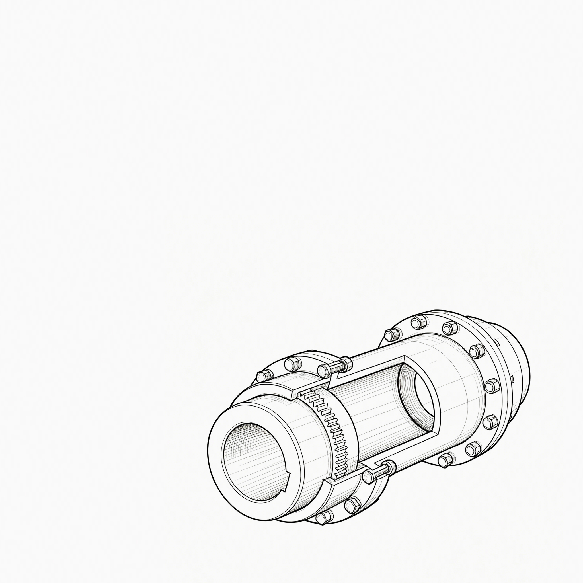

Industrial Couplings: The Definitive Technical Encyclopedia – Classification, Sizing, Failure Prevention, and Lifecycle...
READ MORE
What makes a diaphragm coupling more suitable than a gear coupling for high-speed turbomachinery applications?
Admin 2026-08-20Content
- 1 Why Diaphragm Coupling Wins in High-Speed Turbomachinery
- 1.1 How Torque Transmission Differs Between the Two Coupling Types
- 1.2 Lubrication: The Single Biggest Reliability Factor
- 1.3 Balance and Vibration Behavior at High Speed
- 1.4 Misalignment Capacity: Different Mechanisms, Different Trade-offs
- 1.5 Restoring Forces and Rotor Dynamics
- 1.6 Service Life and Failure Mode Comparison
- 1.7 Lifecycle Cost Considerations
- 1.8 When a Gear Coupling May Still Be Appropriate
- 1.9 Practical Selection Checklist
- 1.10 Conclusion
Rotating Equipment Engineering
Why Diaphragm Coupling Wins in High-Speed Turbomachinery
A close look at how elastic diaphragm flexing outperforms sliding gear teeth once rotational speed, lubrication risk, and lifecycle cost enter the equation.
The diaphragm coupling is generally more suitable than a gear coupling for high-speed turbomachinery because it transmits torque through elastic flexing of thin metal diaphragms rather than through sliding, lubricated gear teeth. This design eliminates the need for continuous lubrication, removes backlash, reduces unbalance at high rotational speeds, and delivers a longer maintenance-free service life. For applications such as centrifugal compressors, gas turbines, and steam turbines that routinely operate above 10,000 rpm, these characteristics translate into fewer unplanned shutdowns, lower lifecycle costs, and more predictable dynamic behavior.
This article breaks down the specific mechanical, operational, and economic reasons a diaphragm coupling outperforms a gear coupling in demanding high-speed rotating equipment, supported by comparative data and practical selection guidance.
How Torque Transmission Differs Between the Two Coupling Types
A gear coupling transmits torque through meshing gear teeth on a hub and sleeve, which slide relative to each other whenever there is angular or parallel misalignment. This sliding action generates friction and heat, and it requires a continuous supply of grease or oil to prevent premature wear of the tooth flanks.
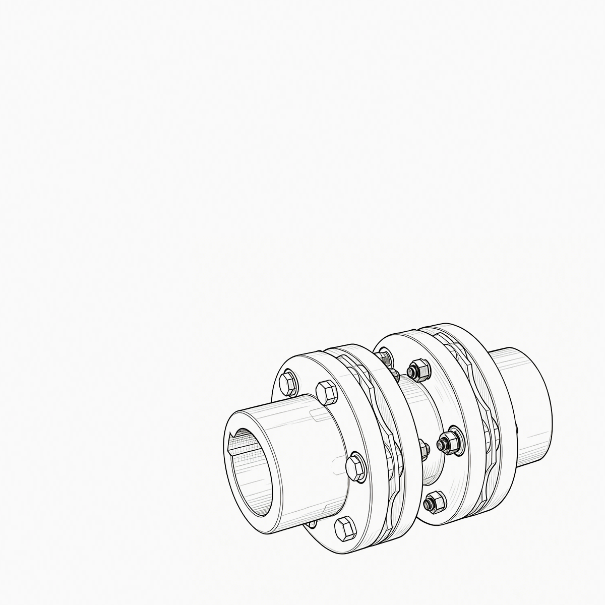
A diaphragm coupling, by contrast, transmits torque through one or more thin, contoured metal diaphragms bolted directly between the driving and driven hubs. Misalignment is accommodated by the diaphragm flexing elastically rather than by parts sliding against one another. Because there is no relative sliding motion between load-carrying components, there is no need for lubrication and no wear-related torque loss over time.
Info
At speeds above 10,000 rpm, even small amounts of frictional heating or lubricant degradation in a gear coupling can lead to tooth flank scoring, uneven wear, and a gradual increase in dynamic unbalance. A diaphragm coupling avoids this failure path entirely, which is why it is the default choice in most modern turbine and compressor trains.
Lubrication: The Single Biggest Reliability Factor
Lubrication dependency is often the deciding factor when engineers compare a diaphragm coupling against a gear coupling. A gear coupling requires periodic regreasing, typically every 3 to 6 months for continuous-duty service, and any lapse in this schedule accelerates wear and can cause catastrophic tooth failure. Grease also tends to migrate outward under centrifugal force at high rpm, a phenomenon known as grease separation, which leaves tooth flanks under-lubricated precisely when speeds are highest.
A diaphragm coupling has no lubricated wear interface, so it is classified as a "dry" or maintenance-free coupling. This single design difference removes an entire category of failure modes and maintenance tasks from the rotating equipment train.
| Characteristic | Diaphragm Coupling | Gear Coupling |
|---|---|---|
| Lubrication required | No | Yes, every 3–6 months |
| Typical inspection interval | 12–24 months | 3–6 months |
| Wear-related failure risk | Very low | Moderate to high |
| Backlash over service life | None | Increases with wear |
Balance and Vibration Behavior at High Speed
High-speed turbomachinery is extremely sensitive to rotor unbalance, since unbalance forces increase with the square of rotational speed. A gear coupling's sliding tooth interfaces introduce small amounts of clearance that can shift under centrifugal load, creating unpredictable unbalance that grows as teeth wear. This is one reason many gear couplings are limited to speeds below roughly 8,000 to 10,000 rpm in continuous service without frequent rebalancing.
A diaphragm coupling is a fully bolted, zero-clearance assembly. Because the diaphragm pack flexes elastically rather than relying on loose-fitting teeth, the coupling maintains consistent balance over its entire service life. Diaphragm couplings are routinely used in applications exceeding 20,000 rpm, including integrally geared compressors and aeroderivative gas turbine drivelines, where sustained precision balance is non-negotiable.
Diaphragm couplings are torsionally stiff, meaning they transmit torque with minimal windup or lag — a property that helps maintain accurate torsional response in control loops for compressors and generators, where phase lag can affect surge control and load-sharing accuracy.
Misalignment Capacity: Different Mechanisms, Different Trade-offs
Both coupling types accommodate shaft misalignment, but the mechanisms differ significantly:
- A gear coupling accommodates misalignment through sliding contact between crowned teeth and a mating sleeve, which works well for larger misalignment angles but generates friction with every revolution.
- A diaphragm coupling accommodates misalignment through elastic bending of the diaphragm material itself, with no sliding contact and no friction generated during operation.
- Gear couplings typically tolerate slightly larger angular misalignment, often up to 1 degree per mesh, while diaphragm couplings are usually rated for around 0.25 to 0.5 degrees per diaphragm pack.
- Despite the smaller misalignment window, diaphragm couplings are preferred in precision-aligned turbomachinery trains where alignment is tightly controlled during installation, making the larger capacity of gear couplings unnecessary.
In practice, most high-speed trains are aligned within a few thousandths of an inch during commissioning, so the diaphragm coupling's misalignment range is more than sufficient while offering the added benefit of restoring forces that help center the rotor.
Restoring Forces and Rotor Dynamics
One often-overlooked advantage of a diaphragm coupling is the predictable restoring force it generates when flexed. Because the diaphragm behaves as a calibrated spring element, engineers can model its stiffness precisely in rotor dynamic simulations, improving the accuracy of critical speed predictions for the entire train.
Warning
A gear coupling's restoring force is far less predictable because it depends on friction coefficients between tooth surfaces, which vary with lubricant condition, temperature, and wear state. This unpredictability makes gear couplings harder to model accurately in sensitive rotor dynamic analyses, which is a significant drawback for API 617 and API 671 compliant compressor and turbine trains that require documented lateral and torsional analysis.
Service Life and Failure Mode Comparison
Service life is where the two coupling types diverge most sharply in high-speed applications:
- A gear coupling's life is governed by tooth wear, which is directly tied to lubrication quality, regreasing discipline, and operating speed. Neglected lubrication can reduce service life from years to months.
- A diaphragm coupling's life is governed by material fatigue, since the diaphragm flexes elastically on every revolution. Properly designed diaphragm couplings are engineered for infinite fatigue life within their rated misalignment and torque envelope, meaning they can theoretically operate indefinitely without fatigue-related failure.
- Failure in a gear coupling tends to be gradual, showing up as increasing backlash, vibration, and metal debris in the grease before a full failure. Failure in a diaphragm coupling, if it occurs from overload or fatigue beyond design limits, tends to be a crack propagating through the diaphragm, which is why torque and misalignment limits must never be exceeded.
Danger
Exceeding the rated torque or misalignment envelope of a diaphragm coupling can initiate fatigue cracking in the diaphragm itself. Unlike the gradual wear of a gear coupling, this failure mode offers little early warning, so operating limits must be respected at all times.
Lifecycle Cost Considerations
A gear coupling typically has a lower purchase price than an equivalently rated diaphragm coupling, but the total cost of ownership tells a different story once maintenance labor, lubricant replacement, downtime for regreasing, and premature replacement due to wear are factored in.
Over a typical 15 to 20 year service life of a turbomachinery train, a diaphragm coupling can eliminate dozens of scheduled maintenance interventions, each of which may require partial disassembly, alignment checks, and process downtime. For continuous-duty plants such as refineries, petrochemical facilities, and power generation stations, avoided downtime alone often justifies the higher upfront cost of a diaphragm coupling.
Success
Plants that switch from gear couplings to diaphragm couplings on critical trains typically report a sharp reduction in coupling-related maintenance work orders, along with more stable vibration signatures between planned outages.
When a Gear Coupling May Still Be Appropriate
Despite the advantages of a diaphragm coupling, gear couplings remain a reasonable choice in certain scenarios:
- Lower-speed industrial drives where lubrication maintenance is already part of routine plant procedures.
- Applications requiring larger misalignment tolerance than a diaphragm coupling can accommodate.
- Budget-constrained projects where initial capital cost outweighs long-term maintenance savings.
- Legacy equipment trains already designed around gear coupling envelope dimensions.
However, for new high-speed turbomachinery designs, most engineering specifications now default to diaphragm-style couplings unless a specific constraint dictates otherwise.
Practical Selection Checklist
When evaluating whether a diaphragm coupling is the right fit for a high-speed application, consider the following:
- Operating speed: speeds above 10,000 rpm strongly favor diaphragm couplings.
- Maintenance access: remote or hard-to-access installations benefit from maintenance-free operation.
- Rotor dynamic sensitivity: applications requiring precise stiffness modeling favor the predictable spring rate of a diaphragm coupling.
- Alignment quality achievable during installation and operation.
- Torque and misalignment envelope required by the specific driver and driven equipment combination.
Conclusion
For high-speed turbomachinery, a diaphragm coupling generally outperforms a gear coupling because it removes lubrication dependency, maintains balance and torsional stiffness over its full service life, offers predictable restoring forces for rotor dynamic modeling, and reduces long-term maintenance costs. While gear couplings still have a place in lower-speed or budget-sensitive applications, the reliability and lifecycle economics of diaphragm couplings make them the preferred solution for compressors, turbines, and other critical rotating equipment operating at elevated speeds.
PREV: Diaphragm Couplings: Working Principles, Benefits, and Selection GuideNEXT: What Are the Critical Factors for Selecting the Right Industrial Couplings
Be the First to Know
For exclusive deals and latest offers, sign up by entering your email address below.
News
-
-
A rotating equipment engineer at a steel finishing mill recently described a flexible coupling that had failed twice in...
READ MORE -
China's coupling industry is at a critical historical juncture of transformation from scale expansion to quality and eff...
READ MORE -
Your compressor train is running at 9,800 rpm when the vibration monitor triggers an alarm. The first component your ma...
READ MORE -
Gear Coupling vs. Drum Gear Coupling: The Core Difference The main difference is that "gear coupling" is a broad catego...
READ MORE -
During a routine vibration survey on a high-speed compressor train, engineers found a 4.5 mm/s velocity spike at the mo...
READ MORE


ABOUT US
PRODUCTS
INDUSTRIES
CONTACT US
- Phone: +86-18652865511
- Email: sales@ohmach.com
- Address: No.1, Minying Developing Zone, Zhenjiang, Jiangsu, China
Copyright Zhenjiang Orienthold Machinery Co., Ltd. All Rights Reserved.
 Custom Industrial Shaft Coupling Manufacturers