 English
 русский
 Português
 عربى
عربى
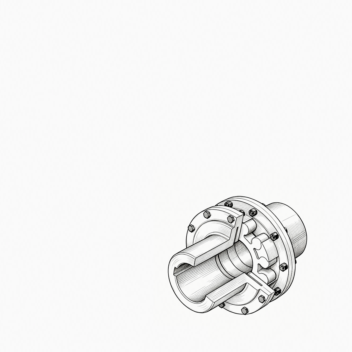
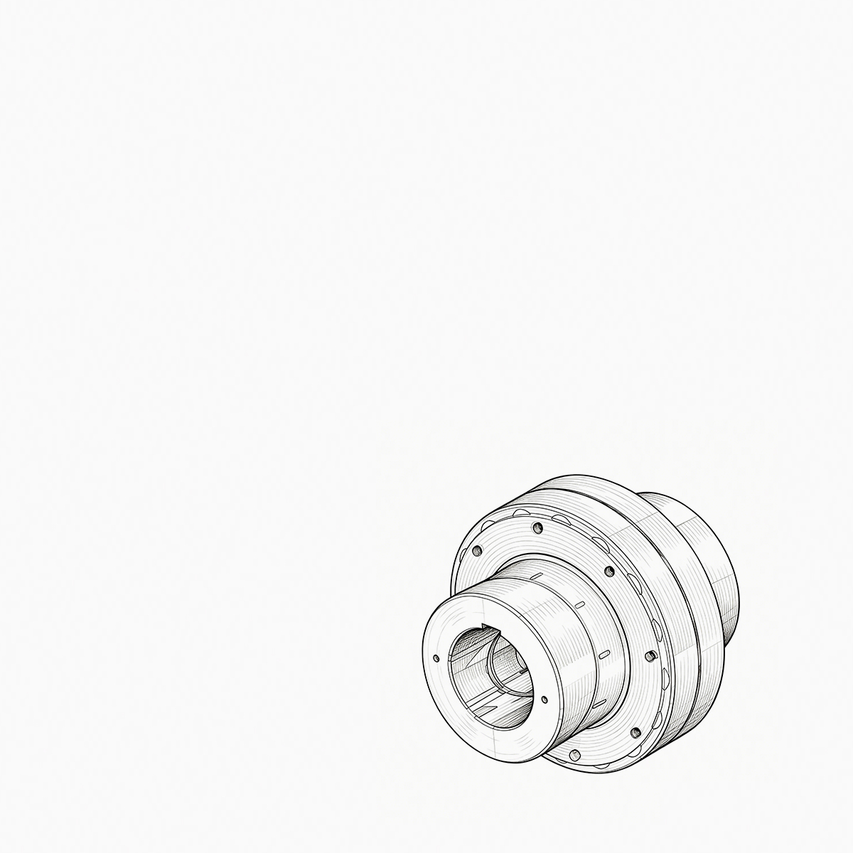
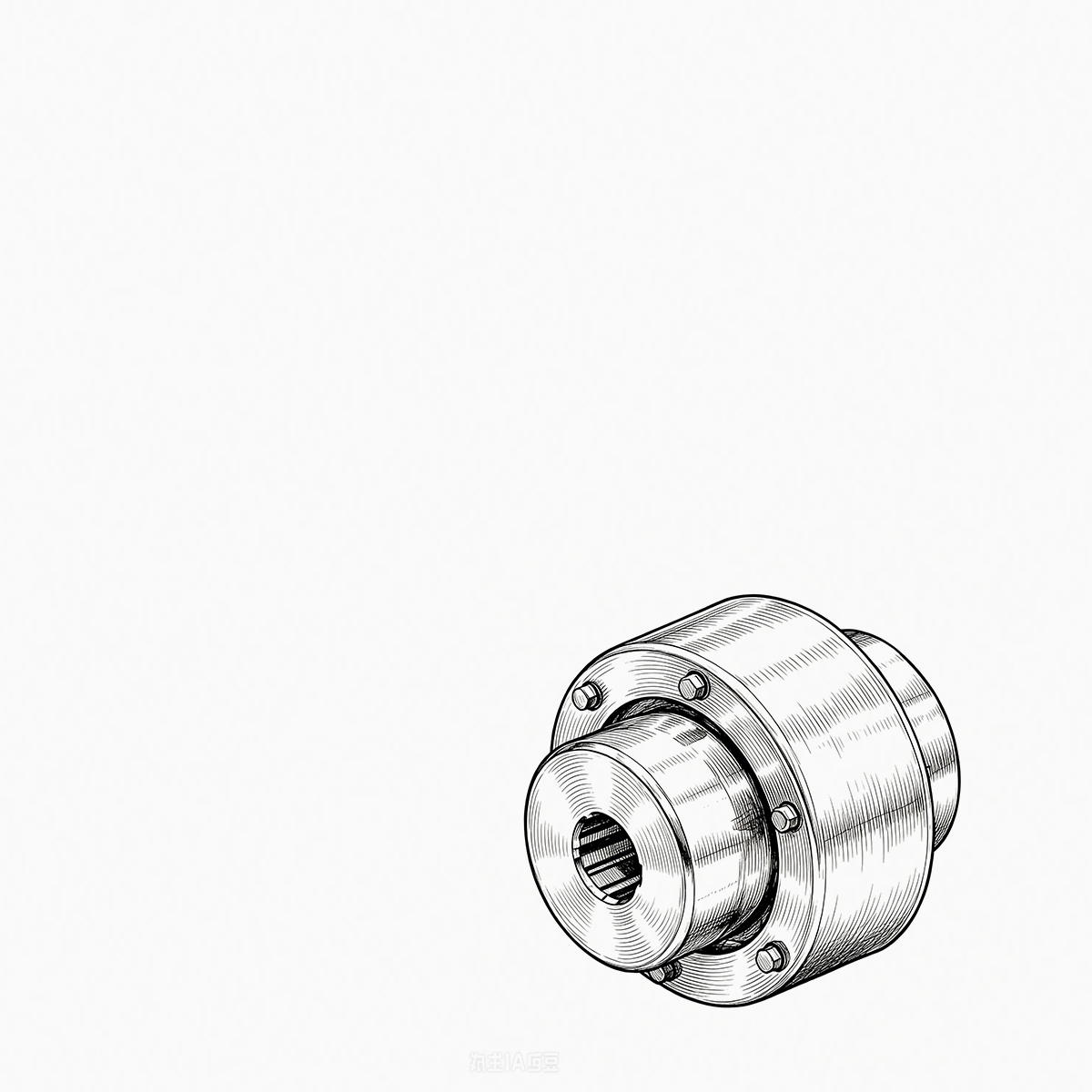
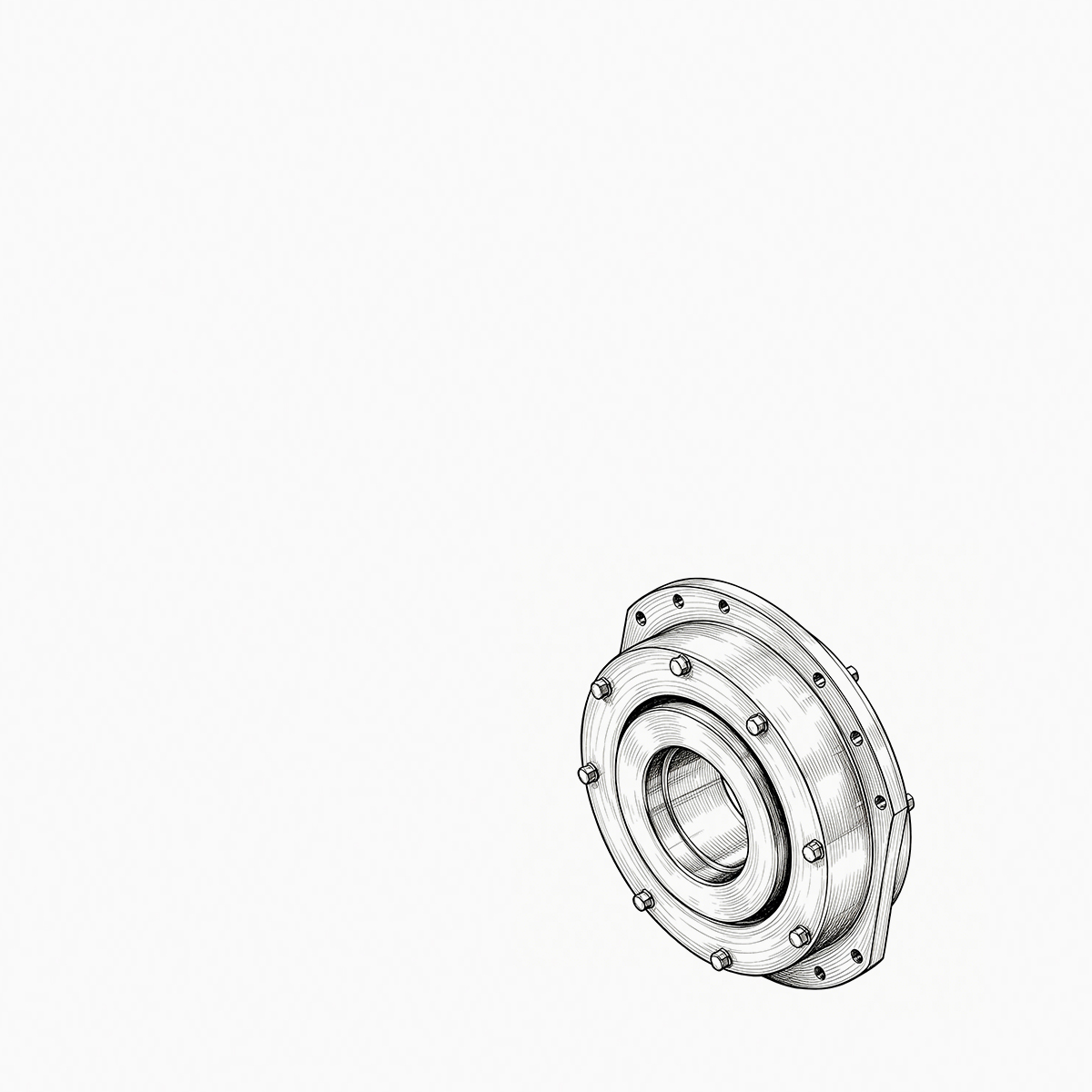
Your compressor train is running at 9,800 rpm when the vibration monitor triggers an alarm. The first component your ma...
READ MORE
Diaphragm Couplings: Working Principles, Benefits, and Selection Guide
Admin 2026-09-03Content
During a routine vibration survey on a high-speed compressor train, engineers found a 4.5 mm/s velocity spike at the motor drive end. The cause was a worn gear coupling, dry from missed lubrication. Replacing it with a diaphragm coupling eliminated the problem for good. Diaphragm couplings are non-lubricated, flexible metal couplings that tolerate misalignment while transmitting full rated torque. They have become the default choice for high-speed rotating machinery, not because they are new, but because they solve real operational issues.
What Is a Diaphragm Coupling?
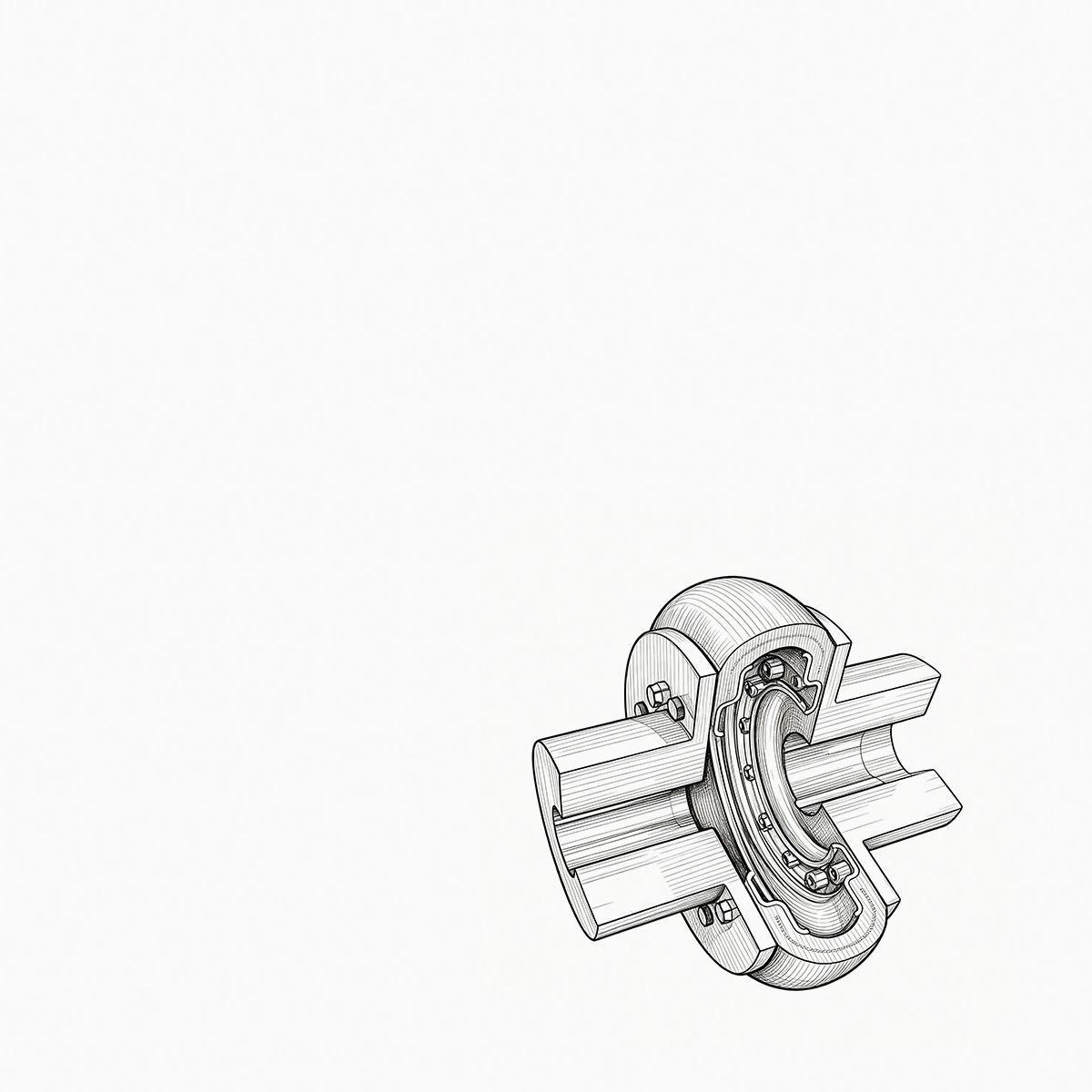
A diaphragm coupling connects two shafts using one or more thin metallic diaphragms. Torque flows from the driving flange through the flexing diaphragm into the driven flange. The diaphragm is designed to bend in a controlled way, which lets it absorb angular misalignment, parallel offset, and axial displacement without sliding parts or backlash.
Unlike gear couplings, diaphragm couplings do not rely on lubricated teeth. The metal flexure works through elastic deformation, so there is no frictional wear. This gives several practical benefits:
- No lubrication or sealing system required, reducing maintenance and eliminating oil leaks.
- Wide operating temperature range, typically from -40 °C to over 250 °C depending on material.
- Smooth torque transmission with no periodic tooth mesh noise.
- No backlash, making them suitable for precision and reversing drives.
- Predictable torsional stiffness, which helps avoid critical speed issues in high-speed trains.
Diaphragm Coupling vs. Gear Coupling: Key Differences
The most frequent comparison in rotating-equipment design is between gear couplings and diaphragm couplings. The table below summarizes the differences that matter most in service.
| Feature | Diaphragm Coupling | Gear Coupling |
|---|---|---|
| Lubrication | None required | Grease or oil required |
| Wear mechanism | Elastic flexure, no wear | Tooth sliding, progressive wear |
| Maintenance interval | Inspect flex element periodically | Relubricate at regular intervals |
| Misalignment capacity | Moderate angular and offset, no backlash | High angular, but with sliding wear |
| High-speed capability | Excellent, no lubricant churning | Good, but lubrication becomes critical |
| Fail mode | Predictable fatigue crack | Tooth wear and seizure |
For a deeper engineering comparison, read why a diaphragm coupling is often more suitable than a gear coupling.
Single-Disc, Double-Diaphragm, and Intermediate-Shaft Designs
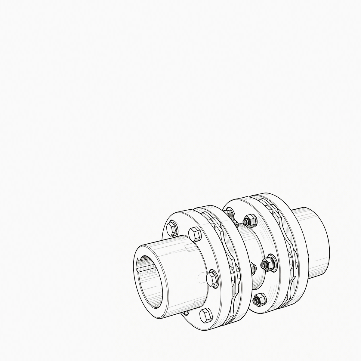
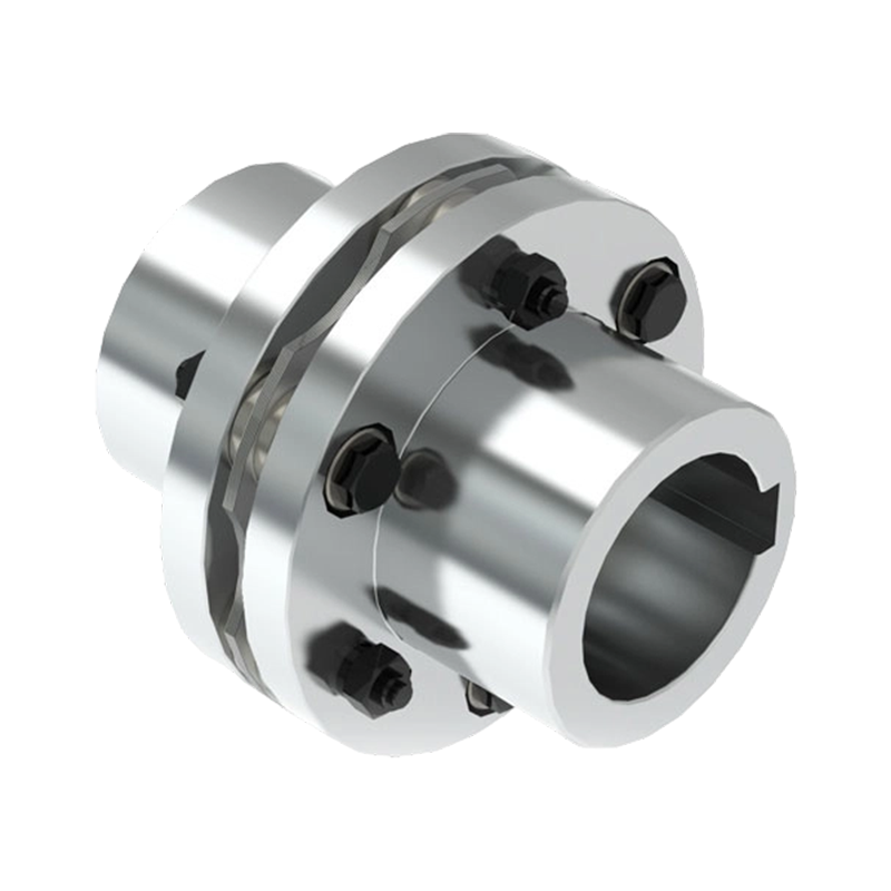
Diaphragm couplings are built in several configurations. A single-disc unit has one flexing element and handles moderate angular misalignment. When you need greater parallel offset or more compliance, a double-diaphragm coupling uses two flexing elements separated by a center spacer. This is the most common industrial configuration because it allows both angular and offset compensation without generating large reaction forces on the bearings.
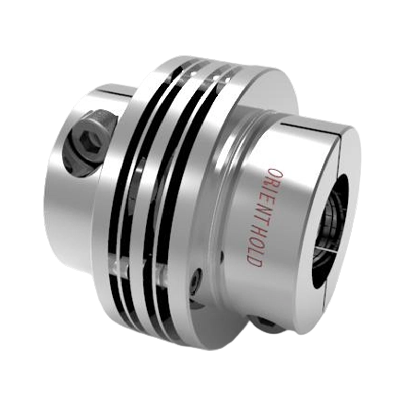 JMII Double-Diaphragm Coupling for Compact Industrial TransmissionsThis stainless steel disc coupling uses two flexing elements and a center spacer to handle angular and parallel misalignment. Its compact one-piece design suits short transmission distances in pumps, machine tools, and automation systems.View Product →
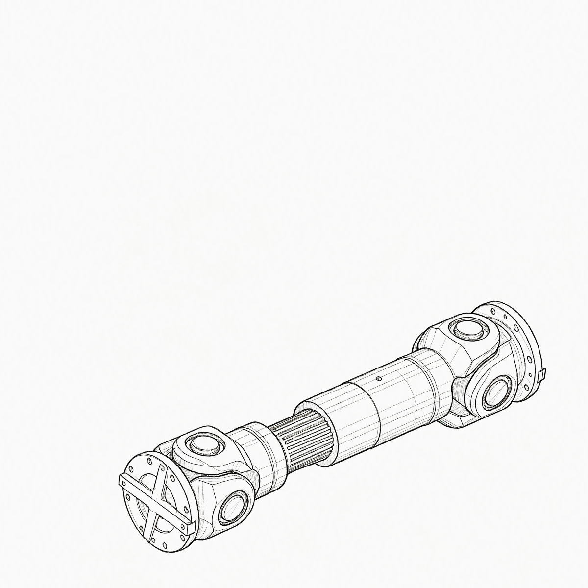
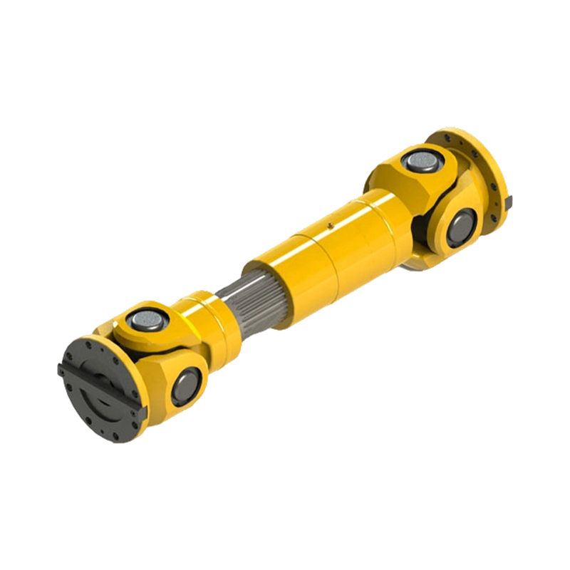
For longer spans between machines, a diaphragm coupling with an intermediate shaft joins two diaphragm packs with a lightweight tube. This arrangement lets engineers cover large distances, keep the system balanced, and reduce overall weight compared to a one-piece solid shaft. It is widely used in pump and motor trains, cooling towers, and generator sets.
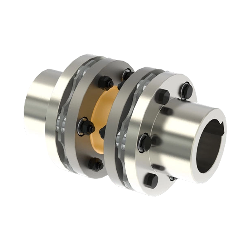 JMIJ Diaphragm Coupling with Intermediate Shaft for Long SpansThis coupling joins two diaphragm packs with a lightweight intermediate shaft, enabling long-distance torque transmission while reducing weight and maintaining balance. It is ideal for pump-motor trains, cooling towers, and generator sets.View Product →
Both designs share the same maintenance-free principle: the metal diaphragm flexes elastically, returns to its original shape when load is removed, and never needs greasing. The choice between them depends on the span and the required misalignment capacity.
How to Select a Diaphragm Coupling
Selecting the correct diaphragm coupling is a straightforward process if you cover the following application data:
- Rated torque and service factor — calculate the actual transmitted torque and apply a factor for shock loads, starting frequency, and speed.
- Operating speed — verify that the coupling’s maximum speed is higher than the maximum machine speed, and check critical speed margins for high-speed trains.
- Misalignment requirements — define angular, parallel, and axial displacements expected from thermal growth, foundation settlement, or manufacturing tolerances.
- Bore sizes and keyways — match the coupling bore to both shaft diameters; custom bores are common and should be specified at order.
- Space envelope — measure the distance between shaft ends and the available radial space.
- Environment — consider temperature, humidity, chemical exposure, and washdown requirements. Stainless steel diaphragms and fasteners can be specified for corrosive areas.
- Balance quality — for high-speed or precision drives, specify a balance grade such as G2.5 or G1 per ISO 21940.
When these parameters are known, engineering teams can calculate the coupling size using the manufacturer’s torque and misalignment ratings. Because the flex element is not a wearing part, the same coupling can often be reused in a new installation, provided the bore adaptors and spacing are verified.
Where Diaphragm Couplings Are Used
Diaphragm couplings appear wherever reliability and cleanliness matter. They are the standard choice for compressors, pumps, generators, gas turbines, and other high-speed rotating equipment. The chemical, petrochemical, marine, and power generation sectors use them because they eliminate oil leaks and reduce maintenance in remote or hard-to-access locations. In heavy industries such as steel and mining, diaphragm couplings are increasingly used on drives that previously relied on gear couplings, especially where downtime costs are high.
Custom coupling manufacturers serve these industrial sectors with bore-machined and balanced units, often built to match an existing envelope without changing the machinery. A well-made diaphragm coupling can last for years without any intervention beyond periodic visual inspection.
Installation and Maintenance Considerations
Installation quality has a strong effect on diaphragm coupling life. The flex element allows a certain amount of misalignment, but it is not a license for crude alignment. Always follow these practices:
- Align shafts at operating temperature where possible; thermal growth changes the cold alignment values.
- Verify axial spacing so that the diaphragm pack works within its intended axial travel range.
- Tighten hub and flex-element bolts to the manufacturer’s specified torque using a calibrated torque wrench.
- Check bolt clearance holes for proper fit; a diaphragm coupling is sensitive to uneven bolt clamping.
- After installation, rotate the assembly slowly and measure runout at the outside diameter of the flanges.
Periodic maintenance is limited to inspecting the diaphragm for cracks, corrosion, and bolt condition. No lubrication is needed, which is why many users convert any troublesome gear-coupled drive to a diaphragm coupling during an overhaul.
Conclusion
Diaphragm couplings deliver a unique combination of no-lubrication service, predictable fatigue life, and clean operation. For high-speed or high-torque machines where downtime is expensive, they have become the preferred alternative to gear couplings. By defining your torque, speed, misalignment, and shaft dimensions, you can select a standard unit or a custom-built diaphragm coupling that will run reliably for years. If you are replacing a worn coupling on a critical drive, the simple change to a maintenance-free diaphragm coupling often removes the root cause of repeated failures.
PREV: Disc Coupling Manufacturers: A Practical Selection Guide for Industrial BuyersNEXT: What makes a diaphragm coupling more suitable than a gear coupling for high-speed turbomachinery applications?
Be the First to Know
For exclusive deals and latest offers, sign up by entering your email address below.
Related products
News
-
-
China's coupling industry is at a critical historical juncture of transformation from scale expansion to quality and eff...
READ MORE -
Industrial Couplings: The Definitive Technical Encyclopedia – Classification, Sizing, Failure Prevention, and Lifecycle...
READ MORE -
Rotating Equipment Engineering Why Diaphragm Coupling Wins in High-Speed Turbomachinery A close look at how elastic dia...
READ MORE


ABOUT US
PRODUCTS
INDUSTRIES
CONTACT US
- Phone: +86-18652865511
- Email: sales@ohmach.com
- Address: No.1, Minying Developing Zone, Zhenjiang, Jiangsu, China
Copyright Zhenjiang Orienthold Machinery Co., Ltd. All Rights Reserved.
 Custom Industrial Shaft Coupling Manufacturers