 English
 русский
 Português
 عربى
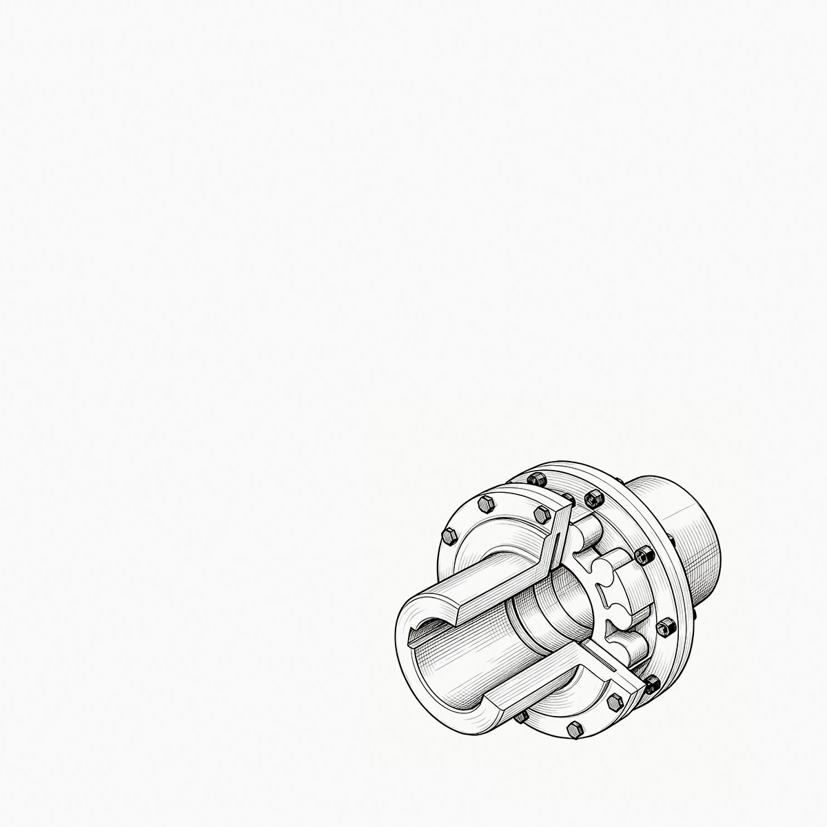
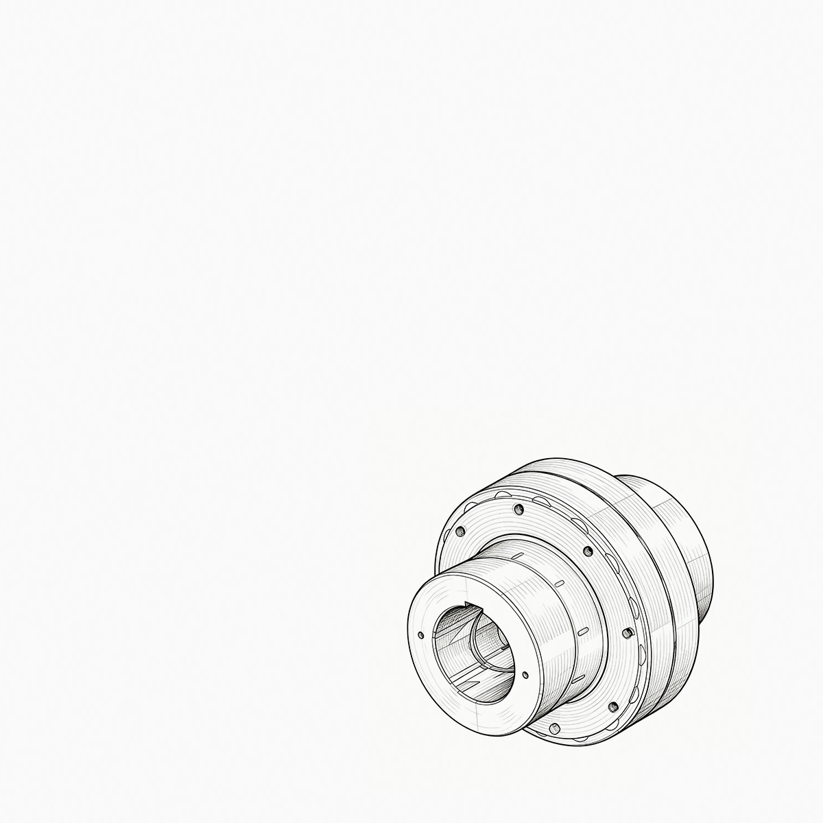
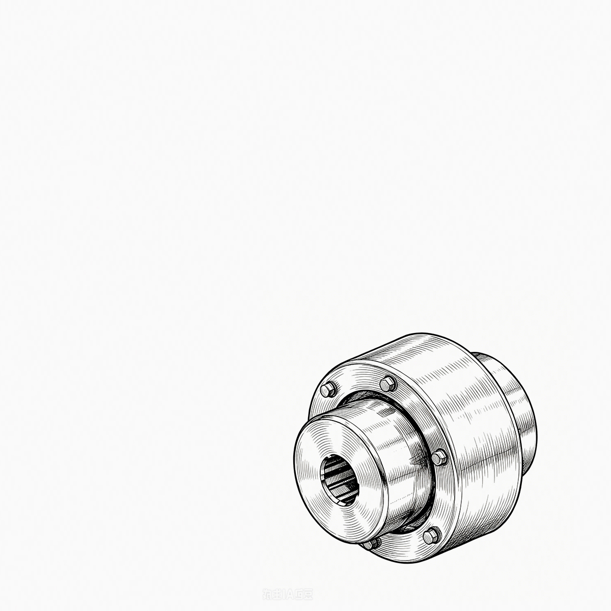
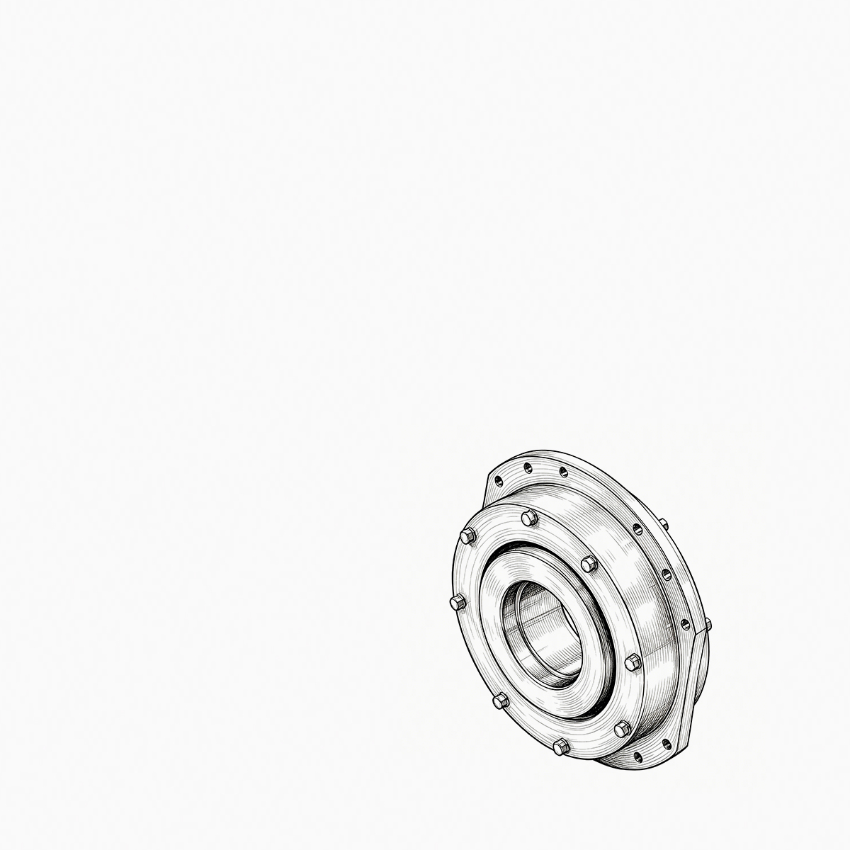
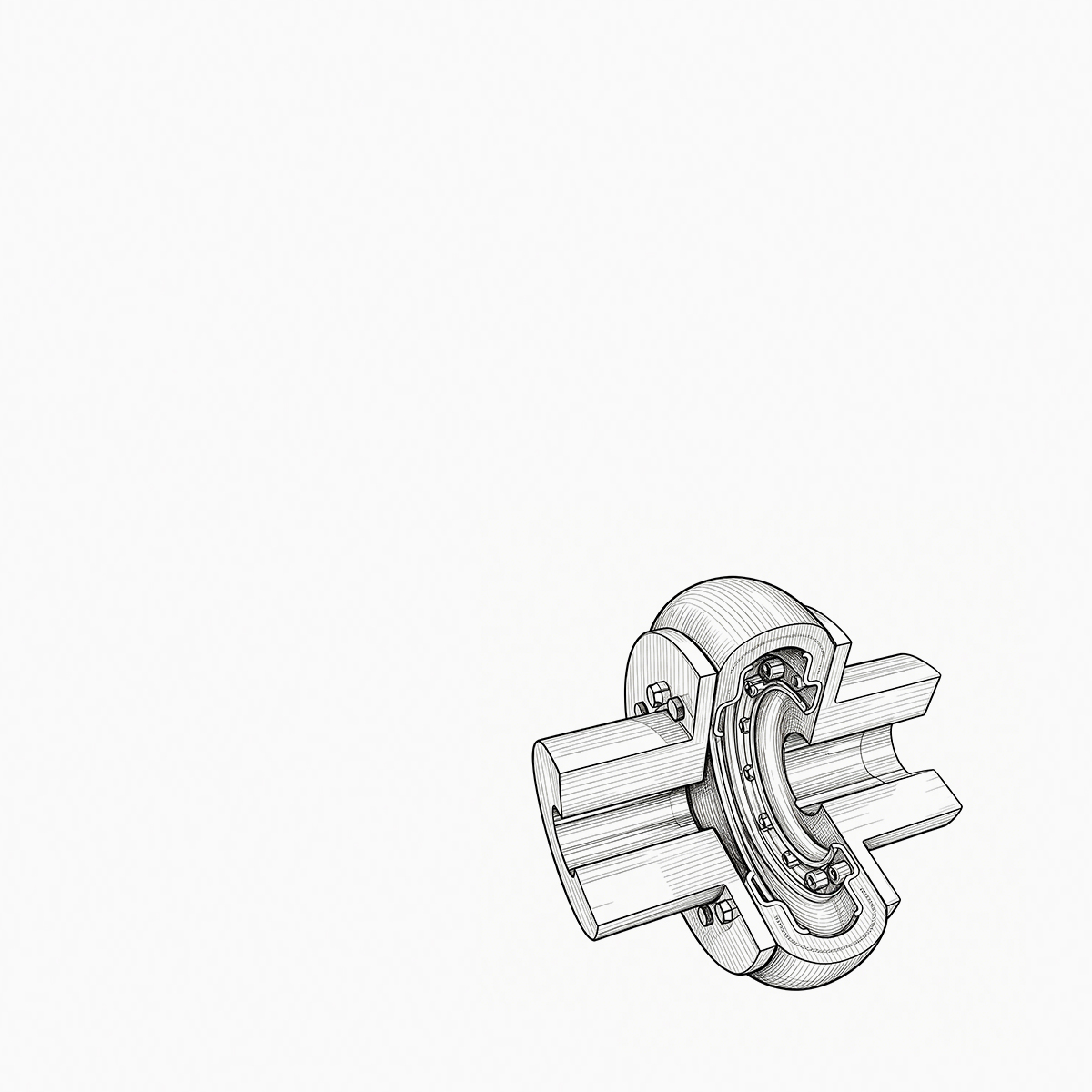
A mill drive rarely fails without warning. It knocks at speed, throws a smear of dark grease around the sleeve flange, ...
READ MORE
Choosing Mechanical Coupling Manufacturers: Types, Testing, and Procurement Guide
Admin 2026-10-29Content
- 1 What Defines a Reliable Mechanical Coupling Manufacturer?
- 2 How Manufacturers Organize Mechanical Coupling Types
- 3 Industry-Specific Demands Guide Vendor Choice
- 4 Testing, Tolerances, and Quality Assurance
- 5 Common Procurement Pitfalls and How to Avoid Them
- 6 How to Shortlist Mechanical Coupling Manufacturers
An equipment buyer in a steel plant once matched a coupling by shaft diameter and catalogue torque. Six weeks later, the hub had fretted, the seal was weeping, and the line had stopped twice. The coupling manufacturer had supplied a standard gear coupling, but the mill drive was reversing, slightly offset, and subject to shock loads. The repair bill was several times the coupling's price. That sequence explains why mechanical coupling manufacturers should be evaluated on engineering depth, not just the parts in their stock list.
That failure was not a random component defect. The coupling was rated for the motor's nominal torque, but the reversing load produced torque spikes above that rating. The misalignment was also outside the gear coupling's designed capability. A manufacturer that asks about duty cycles, misalignment, and ambient conditions would have caught the mismatch before shipment.
What Defines a Reliable Mechanical Coupling Manufacturer?
At a minimum, a capable manufacturer should understand the operating envelope: torque, speed, misalignment, temperature, and cyclic loads. They should be able to explain why a particular tooth profile works and what happens when misalignment exceeds the catalogue rating. They should also control the processes that determine failure modes: machining accuracy, material quality, heat treatment, balancing, and final inspection.
Material selection is a good early indicator. Hubs for high-torque applications are typically forged or high-strength cast steel, not cheap blanks. Heat treatment should be controlled and documented. In gear couplings, the tooth surface hardenability and core toughness affect both wear and crack resistance. A manufacturer that can provide records for every batch is more likely to maintain consistent quality.
Machining tolerances matter as much as materials. Bore diameter, keyway position, flange runout, and face perpendicularity are dimensions that affect dynamic behaviour. A coupling that is out of tolerance will not run silently; it will generate vibration that damages downstream components.
These factors separate a component supplier from a transmission partner:
- Engineering support for selection and customisation
- In-house machining and quality control
- Material traceability and certificates
- Testing equipment and report generation
How Manufacturers Organize Mechanical Coupling Types
Most industrial coupling lines divide first into rigid and flexible types. Flexible couplings are further grouped by load-carrying element: gear teeth, metallic discs, universal joints, or elastomeric elements. The tree below shows a common classification used by coupling manufacturers.
- Rigid couplings
- Sleeve / compression
- Flange
- Flexible couplings
- Involute gear (drum crown) — high torque, moderate misalignment
- Metallic diaphragm — high speed, no lubrication
- Universal joint — large angular travel
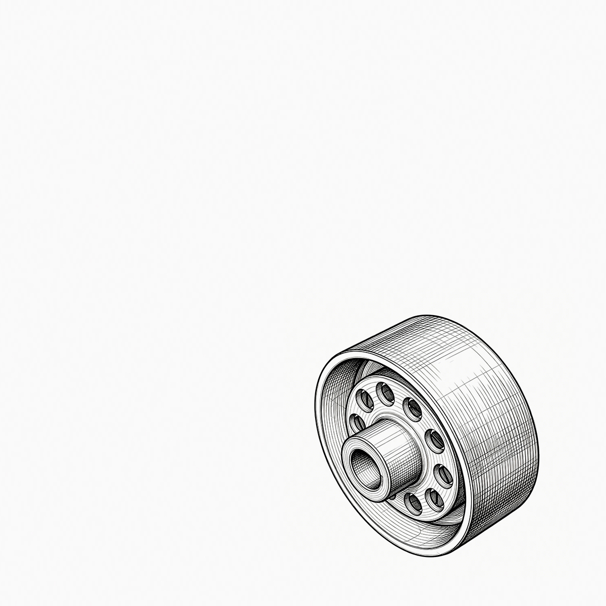
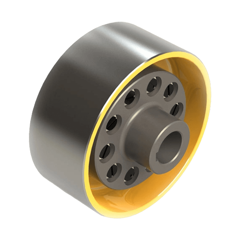
- Elastomeric pin / spider / tire — shock dampening
Drum Gear Couplings
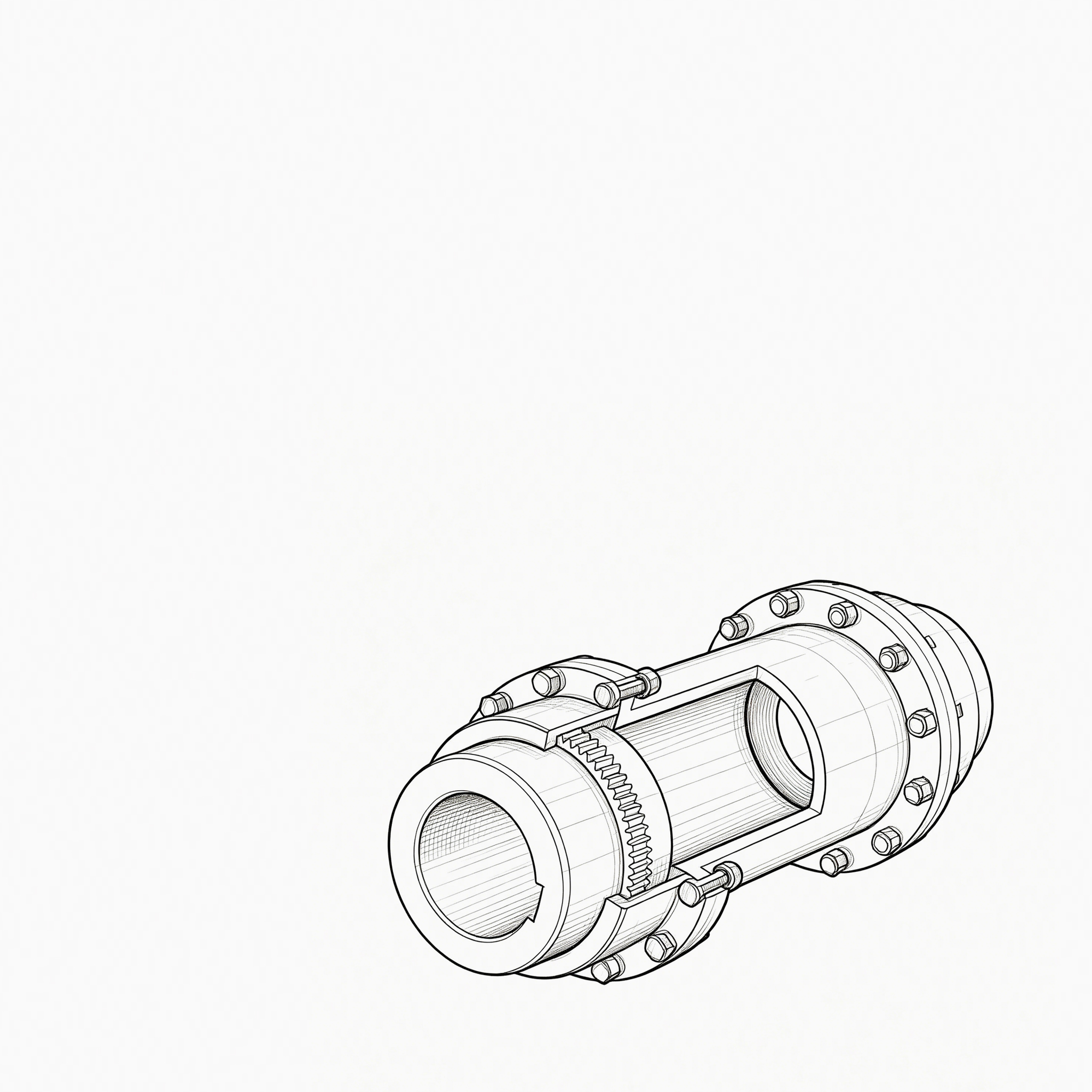
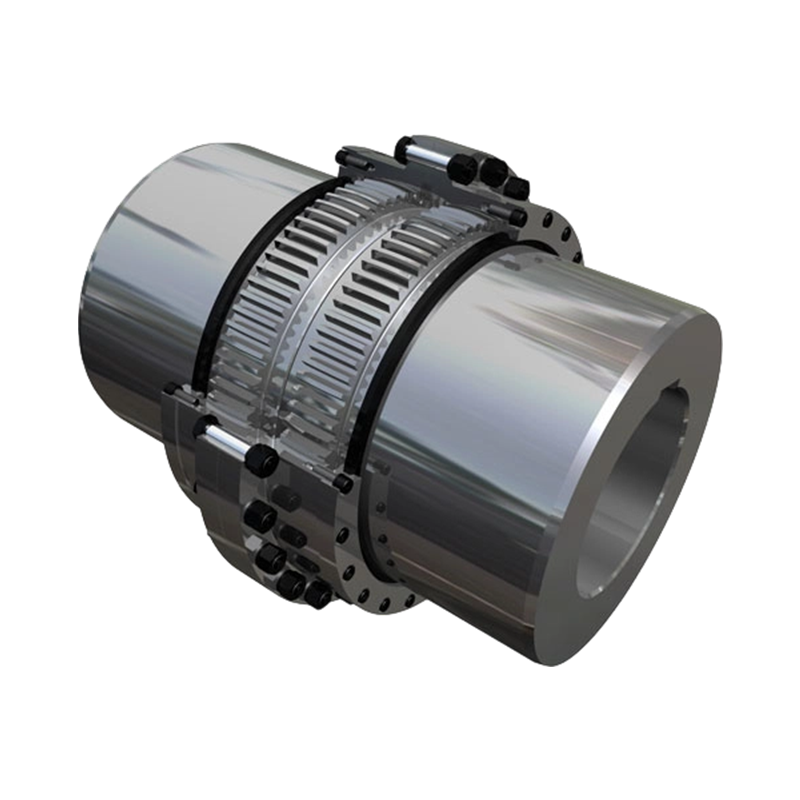
For continuous steel and mining lines, drum gear couplings are common because they offer high torque density and tolerate some angular misalignment. The important detail is the crown form on the external gear; a well-cut crown spreads contact stress and reduces edge loading. For high cyclic loads, the tooth flanks are finished to a barrelled profile, and backlash is controlled so that torque reversal does not produce hammering. Manufacturers that produce their own tooth cutting and hardening are better positioned to control quality.
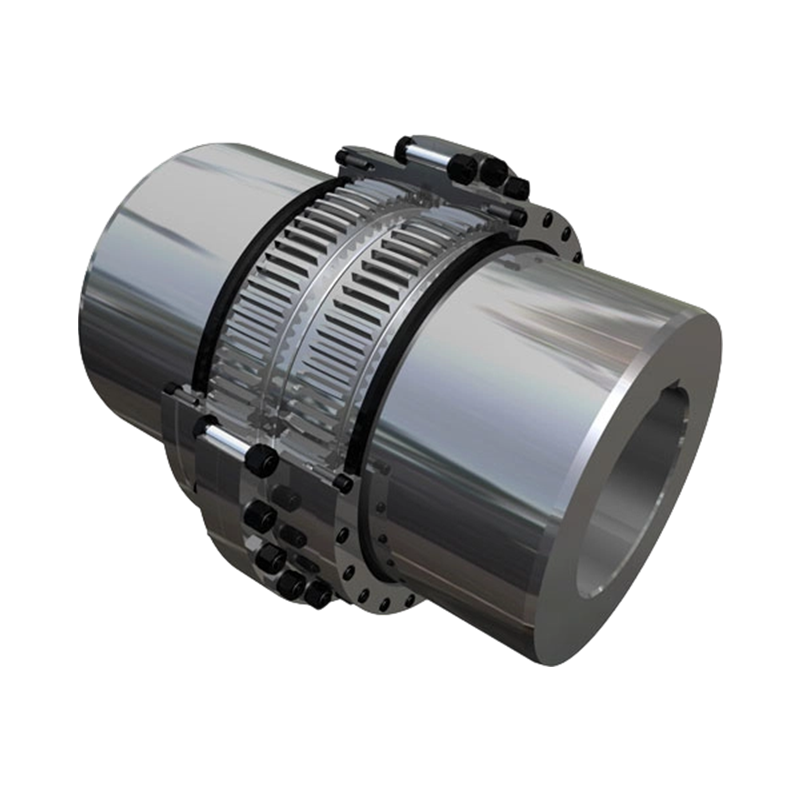 Heavy-Duty GICL Drum Gear Coupling for High-Torque ApplicationsThis crowned-tooth gear coupling handles axial, radial, and angular misalignment under heavy loads, making it ideal for steel and mining lines.View Product →
Diaphragm Couplings
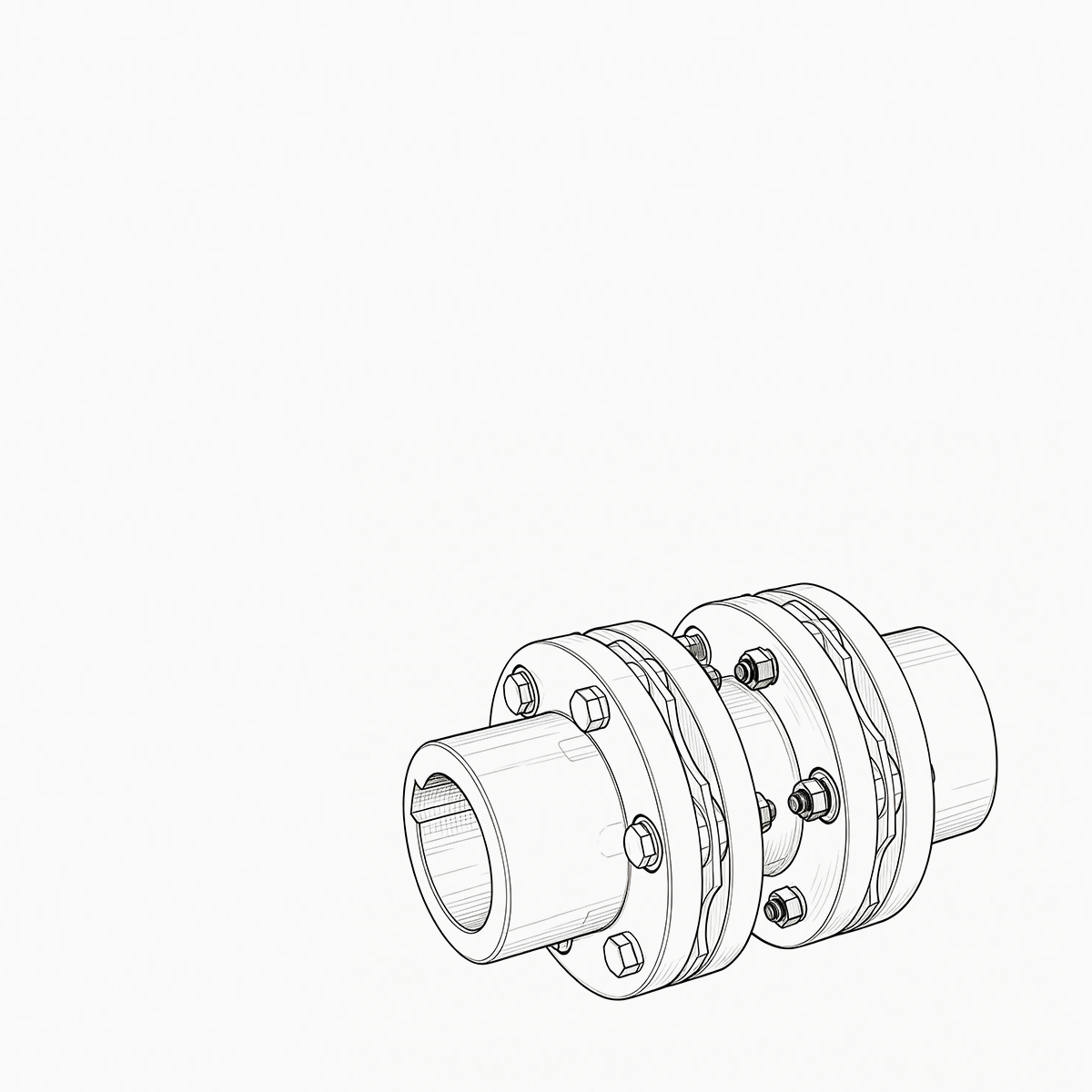
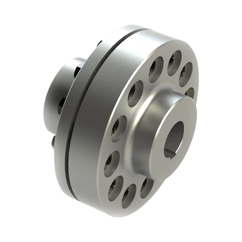
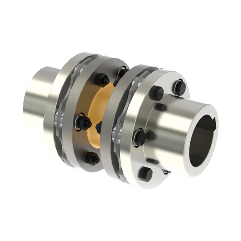
For pumps, compressors, and high-speed machinery, diaphragm couplings avoid lubricant and backlash. They transfer torque through metallic discs that flex elastically. A key reliability factor is the disc profile; fatigue life depends on how the stack is clamped and how edge stresses are minimized. Disc pack materials are usually high-strength stainless or alloy steel, and clamping bolts are torqued to precise values to prevent fretting at the bore.
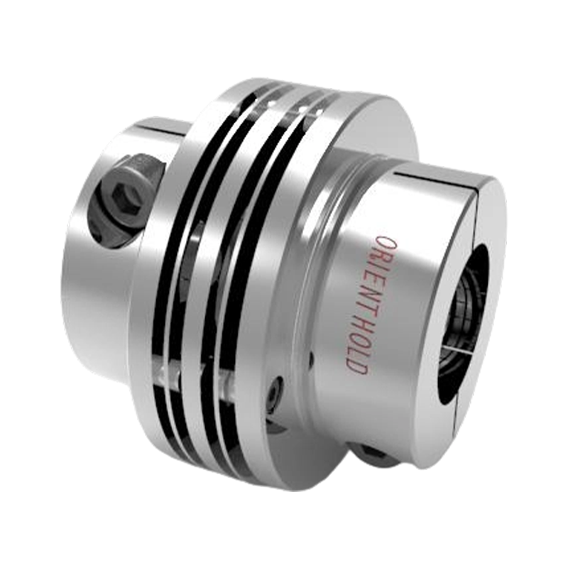 JMII All-Metal Double-Diaphragm CouplingA maintenance-free, backlash-free coupling with stainless steel discs, compensating for misalignment in high-speed, high-precision machinery.View Product →
Universal Joint Couplings
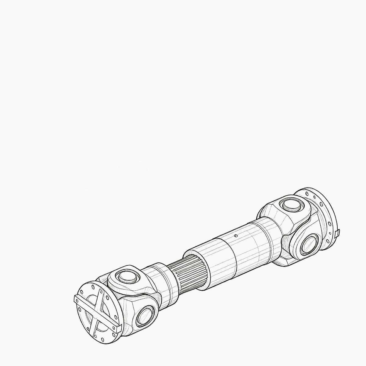
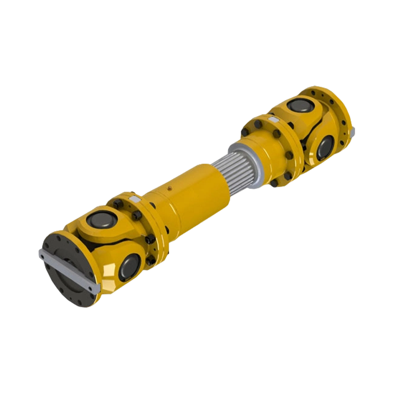
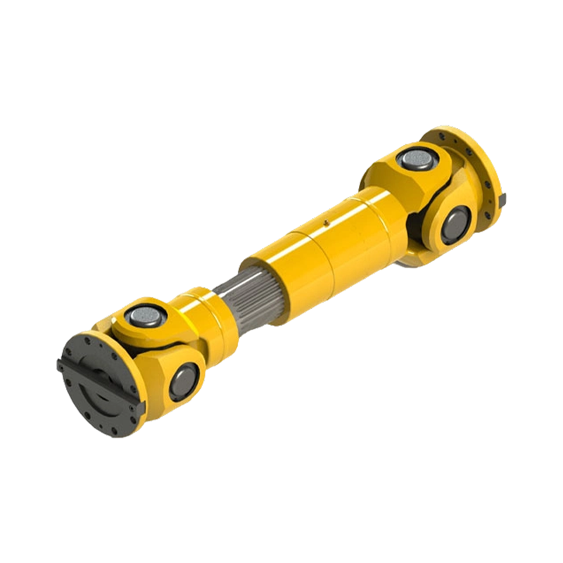
When shafts intersect at an angle or need to move over long distances, universal couplings handle large angular misalignment. Telescopic versions absorb axial displacement, making them useful in rolling mills and marine drives. Joint geometry and bearing selection determine service life. Needle bearings or plain bearings must be sized for the joint angle and speed, and most premature failures come from missing or incorrect lubrication at the yokes.
 SWC-BF Telescopic Flange Universal CouplingCompact universal joint with telescopic adjustment and flange connection, handling large angular misalignment and axial travel in demanding drives.View Product →
| Family | Torque density | Misalignment | Lubrication | Typical use |
|---|---|---|---|---|
| Drum gear | High | Angular / moderate axial | Required | Steel mills, conveyors |
| Diaphragm | Moderate-high | Angular / axial | None | Pumps, turbines |
| Universal joint | High | Large angles | Required at bearings | Rolling mills, marine shafts |
| Elastomeric pin / tire | Moderate | Good for shock | Usually none | Crushers, fans |
Manufacturers that cover several coupling families can usually suggest an alternative if a particular design becomes unavailable or if service conditions change. This breadth also helps when one production line needs different coupling types on separate drives.
Industry-Specific Demands Guide Vendor Choice
One coupling can work in several industries; the right coupling line for a given plant depends on load cycle and environment. In mining, shock loads and dust make cast or forged steel hubs and protected gear surfaces essential. In petrochemical and power generation, high speed and zero lubricant leakage push operators toward diaphragm couplings. In port cranes and construction machinery, frequent starts and stops favour designs with brake wheels or brake discs, often integrated with the coupling housing.
In marine drive shafts, reversing torque and hull deformation create both angular and axial misalignment; universal couplings or flexible disc pack designs are commonly used. In power generation, a diaphragm coupling is often selected for boiler feed pumps because it can operate at high speed without lubrication and has lower axial stiffness for the pump casing.
A responsible supplier will ask for the motor and driven shaft drawings, not just the nominal power. They may also request starting frequency, ambient temperature, and how much alignment error is expected after thermal expansion. For a broader view of how these applications map to coupling families, the industry overview page lists the main sectors served by coupling manufacturers.
Although every application has its own numbers, a relative comparison helps when budgeting. The chart below shows an illustrative index for typical initial cost across coupling families, with an elastomeric pin coupling set at 1.0. The same relative picture applies to maintenance; gear and universal couplings require periodic lubrication and wear inspection, while diaphragm and elastomeric types are closer to fit-and-forget.
Elastomeric pin
1.0
Tire
1.2
Drum gear
2.2
Diaphragm
2.8
Universal
3.4
Testing, Tolerances, and Quality Assurance
A manufacturer's test plan reveals more than its brochure. Routine checks should include hardness tests on gear teeth, dimensional inspection of bores and keyways, magnetic particle inspection on critical hubs, and balancing if the operating speed is above roughly 1,500 rpm. For lightly loaded applications, this may seem excessive, but a single field failure costs far more than the inspection.
The level of testing should match the duty. A small fan coupling at 1,000 rpm may not need a balancing certificate, but a pump at 3,600 rpm or a turbo expander at 12,000 rpm absolutely does. High-speed applications also demand controlled axial clamping lengths and compatible thermal expansion coefficients.
- Material certificates and heat treatment records
- Hardness and microstructure reports
- Dimensional records for bore, keyway, pilot, and flange faces
- Balancing reports for high-speed service
- Non-destructive test reports for castings and forgings
Ask how the manufacturer handles these documents. A clear report package is a useful indicator of daily production discipline. Factory audit questions can be simple: How do you store raw material? Do you check hardness after heat treatment? Do you keep a copy of the dimensional record for each part? Are the balancing machines calibrated? Answers should be direct and verifiable.
Common Procurement Pitfalls and How to Avoid Them
- Buying on catalogue torque alone. The catalogue rating assumes a defined service factor and continuous application. In reversing drives, the actual stress can be double the steady torque, so ask for the application class and calculate the peak torque.
- Ignoring misalignment data. A coupling that handles nominal angular misalignment may fail when thermal growth shifts the machines by a few millimetres. Measure the actual cold and hot alignment conditions before ordering.
- Skipping balance requirements. For high speed, even a small unbalance can create a force large enough to damage bearings. Confirm the balance quality grade, such as G2.5, and ask for a report.
- Treating bore machining as optional. The bore-to-shaft fit controls runout and stress concentration. A loose fit causes fretting; an interference fit that is too tight can crack a thin hub.
- Assuming all drum gear couplings are the same. Different manufacturers use different crown forms, backlash ranges, and hardening depths. Ask for the reference standard and test values.
How to Shortlist Mechanical Coupling Manufacturers
Start by collecting the operating data of your equipment: maximum torque, speed range, misalignment from thermal growth, and the number of starts per hour. Then ask candidates to propose a model and justify it. A shortlist should come from those who ask questions about your process, not those who quote instantly from a price list.
When you discuss selection, good suppliers will ask questions themselves. They will want to know if there are torque spikes, if the shaft has a shoulder, whether the coupling needs to be removed without moving the motor, and whether the site has a maintenance schedule. If a supplier does not ask such questions, they are only pushing a spare part.
- Scope the application data — nominal torque, peak torque, speed range, and misalignment envelope.
- Check that the supplier's product range covers your coupling family.
- Confirm testing and documentation capability.
- Review application engineering support — response time and depth.
- Place a trial order for the most critical drive.
For a deeper discussion of how these factors interact, the article on critical factors for selecting the right industrial coupling provides a step-by-step view.
Mechanical coupling manufacturers differ in the details that keep production lines running: tooth crown geometry, material heat treatment, balancing class, and the willingness to adapt a design to the operating point. A coupling is a small part of the drivetrain, but its failure is disproportionately expensive. Evaluate the manufacturer the same way you evaluate the rest of your rotating equipment, and the total cost of ownership will be far lower.
PREV: Shaft Coupling Suppliers: How to Vet Industrial Manufacturers Before OrderingNEXT: How to Select Industrial Coupling Suppliers: Key Criteria for Reliability
Be the First to Know
For exclusive deals and latest offers, sign up by entering your email address below.
Related products
News
-
-
During a routine vibration survey on a high-speed compressor train, engineers found a 4.5 mm/s velocity spike at the mo...
READ MORE -
Your compressor train is running at 9,800 rpm when the vibration monitor triggers an alarm. The first component your ma...
READ MORE -
A maintenance engineer pulls a failed coupling from a pump drive. The elastomer sleeves are cracked, the pin bolts are ...
READ MORE -
Consider a 250 kW crane hoist that begins to vibrate only when the load is lifted. The drum gear coupling is inspected ...
READ MORE -
China's coupling industry is at a critical historical juncture of transformation from scale expansion to quality and eff...
READ MORE


ABOUT US
PRODUCTS
INDUSTRIES
CONTACT US
- Phone: +86-18652865511
- Email: sales@ohmach.com
- Address: No.1, Minying Developing Zone, Zhenjiang, Jiangsu, China
Copyright © Zhenjiang Orienthold Machinery Co., Ltd. All Rights Reserved.
 Custom Industrial Shaft Coupling Manufacturers