 English
 русский
 Português
 عربى

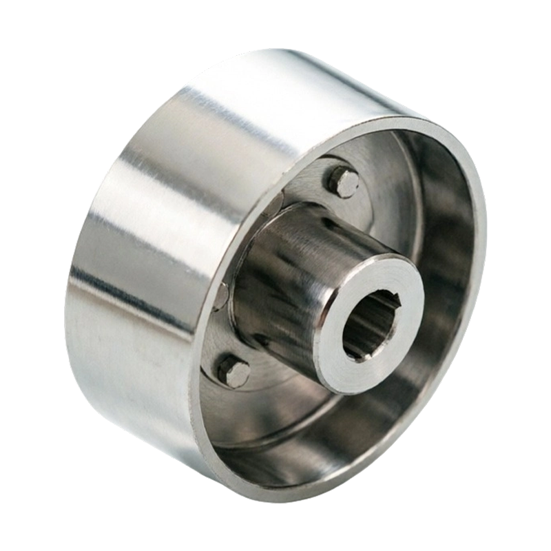
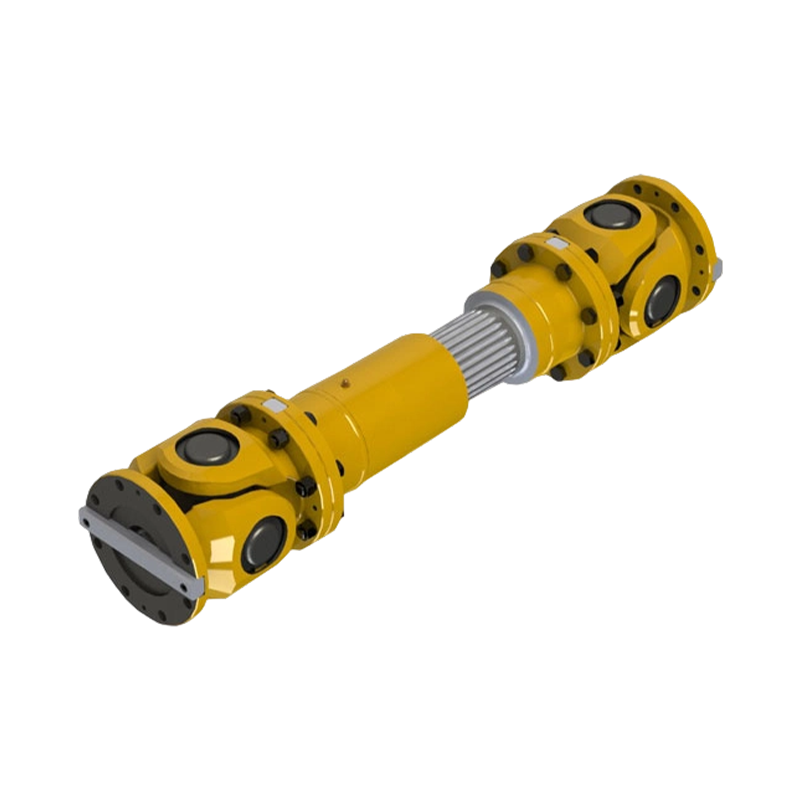
Consider a 250 kW crane hoist that begins to vibrate only when the load is lifted. The drum gear coupling is inspected ...
READ MORE
Drum Gear Coupling Guide: Types, Tolerances, Lubrication, and Buying Risks
Admin 2026-10-15Content
- 1 What a Drum Gear Coupling Actually Is
- 2 Reading the Model Codes: GICL, WG, NGCL and the Rest
- 3 Lubrication and Seals Decide Service Life, Not Torque Rating
- 4 When the Drive Needs a Spacer
- 5 Brake Wheels, Brake Discs and Vertical Mounts
- 6 Bore, Keyway and Balance Tolerances That Cause Rework
- 7 Matching the Coupling Family to the Duty
- 8 A Short Procurement Checklist
A mill drive rarely fails without warning. It knocks at speed, throws a smear of dark grease around the sleeve flange, and vibrates differently as the load swings. When the coupling finally comes off, the sleeve teeth are polished and half the lubricant is gone. In most of those cases the coupling was not undersized at all; the crown radius, the seal class and the lubrication interval were simply never matched to the duty.
The practical answer for most horizontal industrial drives is straightforward. Choose a crowned-tooth drum design, check misalignment at both cold and hot alignment states, and treat grease and seals as scheduled maintenance items rather than an afterthought. The rest of this page explains why that works and where the exceptions sit.
What a Drum Gear Coupling Actually Is
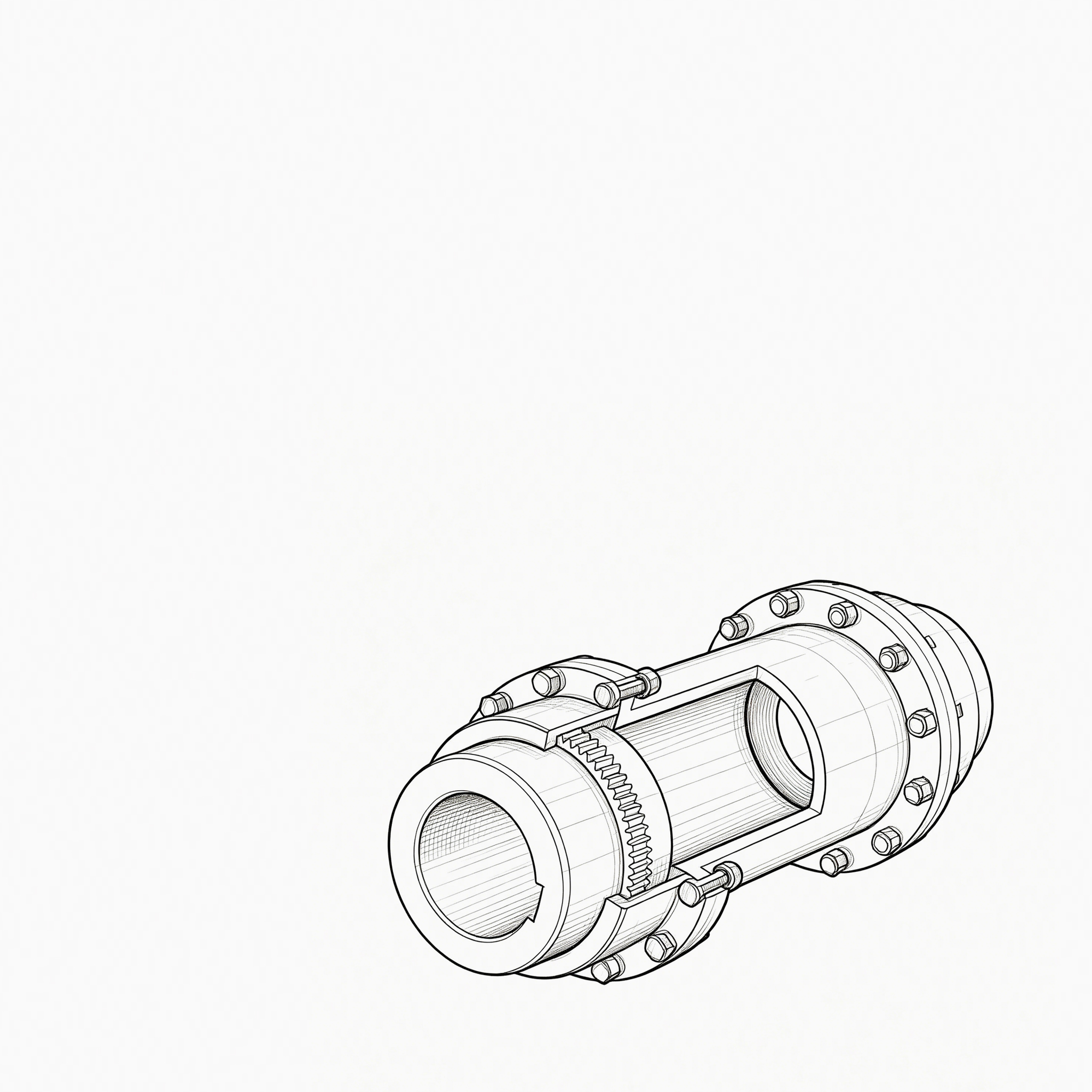
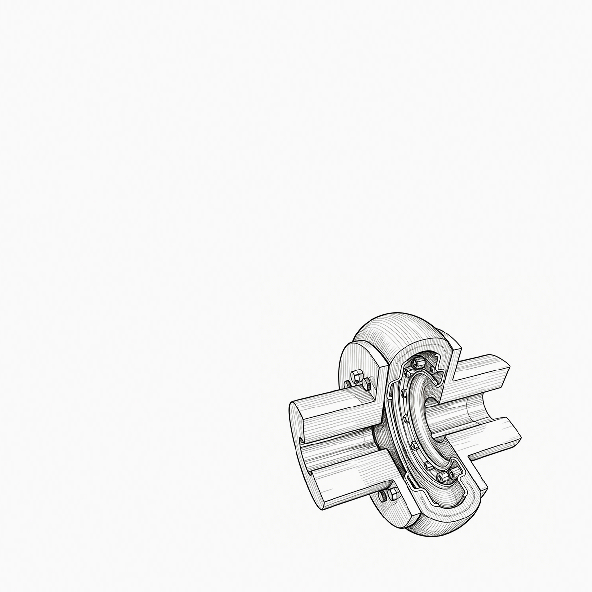
A drum gear coupling connects two shafts through hubs whose external teeth are crowned, meaning barrelled in both the axial and radial direction instead of cut straight. Those teeth mesh with internal teeth inside one or two flanged sleeves. The crown lets each hub pivot slightly inside the sleeve as alignment changes, so the contact patch stays near the middle of the tooth instead of riding the edge.
That single detail drives most purchasing decisions. A straight cylindrical tooth coupling of the same bore and length tolerates roughly a third of the angular misalignment, and it pushes the load onto tooth corners as the shafts move apart. Crowned teeth spread that load and keep the contact zone where the lubricant film actually lives.
Torque capacity is rarely the limiting factor. A properly lubricated drum gear coupling is a high-torque, high-stiffness component, and the failure modes that matter in service are tooth wear, lubricant loss, seal leakage and sleeve cracking. If you are still comparing a standard gear coupling against a drum variant for a specific drive, this comparison of gear coupling versus drum gear coupling walks through the trade-offs in detail.
Typical maximum angular misalignment per coupling, by design:
Rigid flange coupling0 degrees
Straight-tooth gear couplingabout 0.5 degrees
Drum, crowned gear couplingabout 1.5 degrees
Single diaphragm couplingabout 0.5 degrees
Elastomeric jaw or plum couplingabout 1 degree
Tire couplingabout 3 degrees
Indicative values only. Real limits depend on size, series and the published data of the specific manufacturer.
Reading the Model Codes: GICL, WG, NGCL and the Rest
Codes such as GICL, GIICL, NGCL, WG, WGZ and WGT look interchangeable on a quotation sheet, but each prefix answers a different question. The first question is tooth form, the second is how the coupling mounts and what it carries, and the third is whether the drive needs extra axial length.
In this range, the GICL and GIICL families cover the general-purpose crowned-tooth designs, NGCL adds heavier general duty, and the WG family covers the basic bolted-flange crown gear unit. GCLD is listed as a straight cylindrical tooth alternative, which suits drives where misalignment is genuinely small and cost matters more than flexibility. Everything else is a configuration change rather than a different working principle.
Drum gear coupling family
Basic horizontal, bolted flange
WG - basic crown gear coupling, general drive duty
GICL and GIICL - wider bore and torque coverage
NGCL - heavy general duty
Brake integrated
WGZ - crown gear coupling with brake wheel
WGP - crown gear coupling with brake disc
NGCLZ - extended hub with brake wheel
Space and orientation
WGT - crown gear coupling with intermediate spacer
WGC - vertical mounting
Straight-tooth alternative
GCLD - cylindrical teeth, tighter alignment window
Before ordering, confirm the mounting style rather than the prefix. Two couplings with the same bore and torque rating can differ completely in spacer length, brake interface and lubrication method, and those differences decide whether the unit drops straight onto the shaft or becomes a rework job.
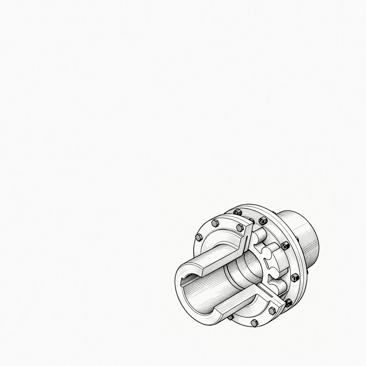
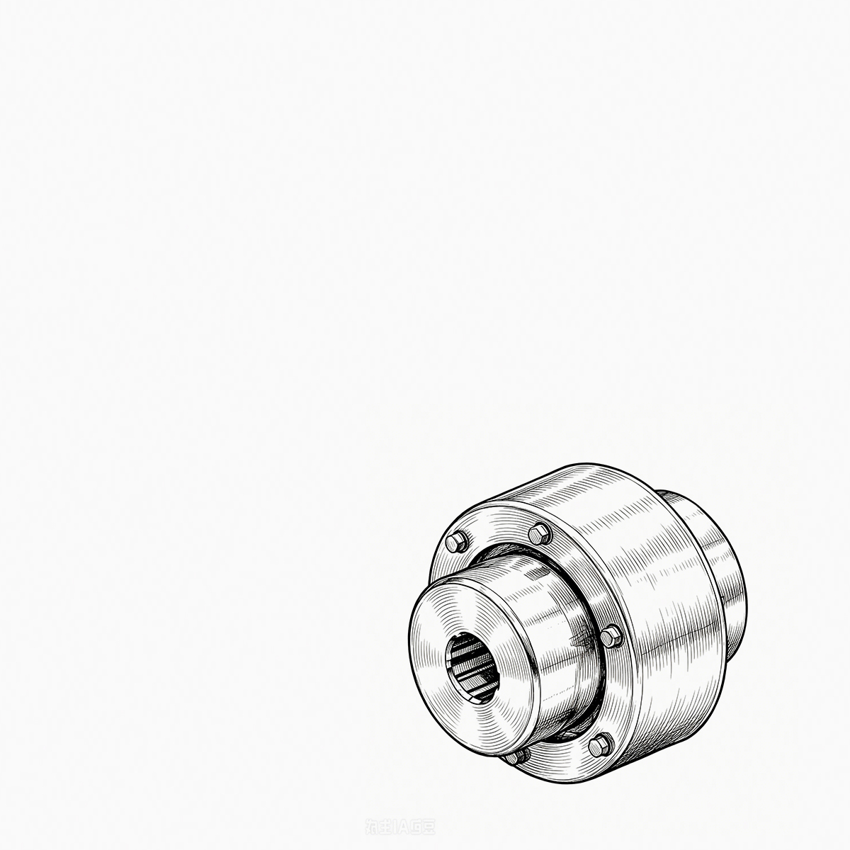
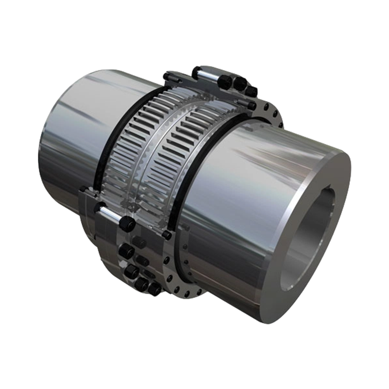
 WG Type Basic Crowned-Gear Coupling for Heavy-Duty DrivesReview this heavy-duty crowned-gear coupling when mounting style and lubrication path matter for reliable torque transmission in demanding industrial drives.View Product →
Lubrication and Seals Decide Service Life, Not Torque Rating
Two couplings with identical torque ratings can deliver service lives that differ by a factor of three, and the reason is almost always the lubricant path and the seal. Grease-filled units dominate general industry because they are simple and forgiving, but grease only works while the seal keeps it in place. Once the O-ring or flange gasket hardens, centrifugal force pushes grease out of the tooth mesh and wear accelerates.
Worth fixing on the specification sheet before the order is placed:
- Grease grade and base oil viscosity matched to the ambient and operating temperature range, not a generic note.
- Seal type stated explicitly: single O-ring, double seal or labyrinth, plus whether the drive sees dust, washdown or oil mist.
- A replenishment interval in operating hours, agreed in writing; a twelve-month calendar interval means nothing on a drive running 8,000 hours a year.
- Whether the hub end caps allow re-greasing without pulling the coupling out of the train.
Oil-lubricated drum gear couplings remove the grease-loss problem but introduce another one: the coupling becomes an oil-retention device. Vertical shafts and drives with large axial movement need the oil circuit and drain position confirmed at the drawing stage, not on site.
When the Drive Needs a Spacer
Maintenance access, not torque, usually pushes a project toward a spacer coupling. If a pump or gearbox must be lifted out without moving the motor, the coupling has to span the gap between the two shaft ends while the hubs stay properly engaged. A crown gear coupling with an intermediate spacer does that job while keeping crowned tooth contact at both ends of the assembly.
Two figures need to be fixed on the drawing: the spacer length required for the removal path, and the permissible residual unbalance if the drive runs above roughly 1,500 rpm. Spacer length affects critical speed and balance far more than it affects torque capacity.
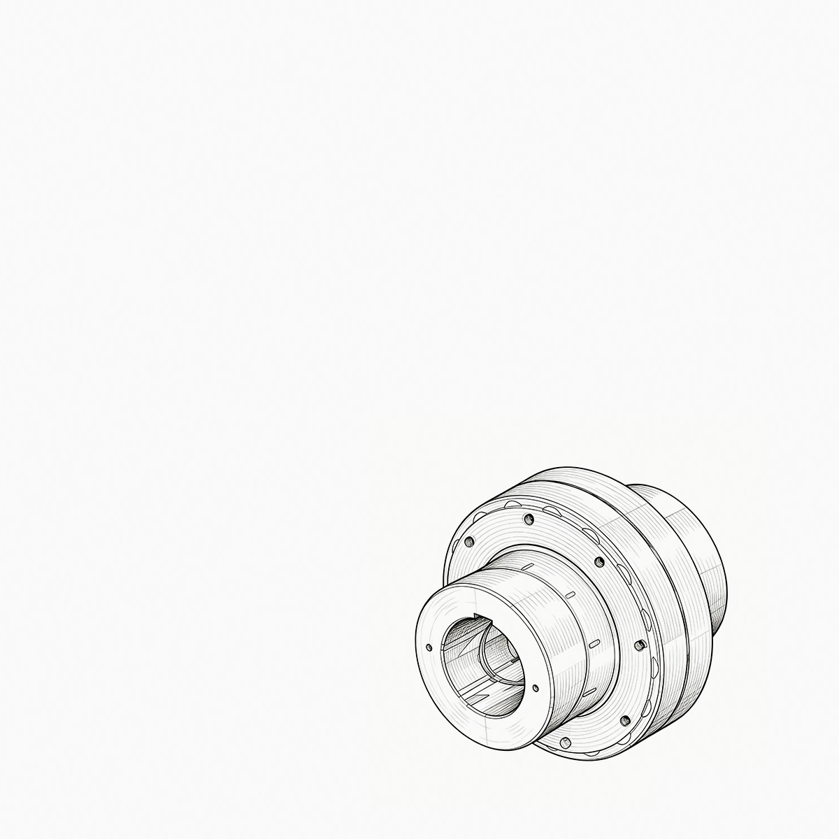
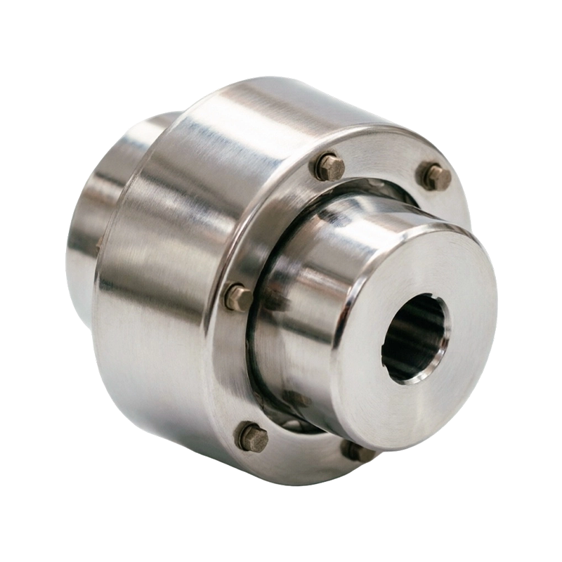
 WGT Crowned-Gear Coupling with Intermediate SpacerUse this long-shaft coupling where spacer length and residual unbalance shape alignment, balance, and stable torque transmission in separated drive systems.View Product →
Brake Wheels, Brake Discs and Vertical Mounts
Crane travel and hoist drives, mill tables and many positioning axes need a braking surface built into the coupling rather than added as a separate component on a second mounting plane. Brake-integrated crown gear couplings place the wheel or disc on one sleeve, so the coupling and the brake share a single interface. Specify brake drum diameter and face width, the distance from the shaft end to the brake face, and whether the wheel sits on the motor side or the gearbox side.
If a drawing shows the brake wheel positioned by a tolerance rather than a hard dimension, expect to adjust brake shoes on site.
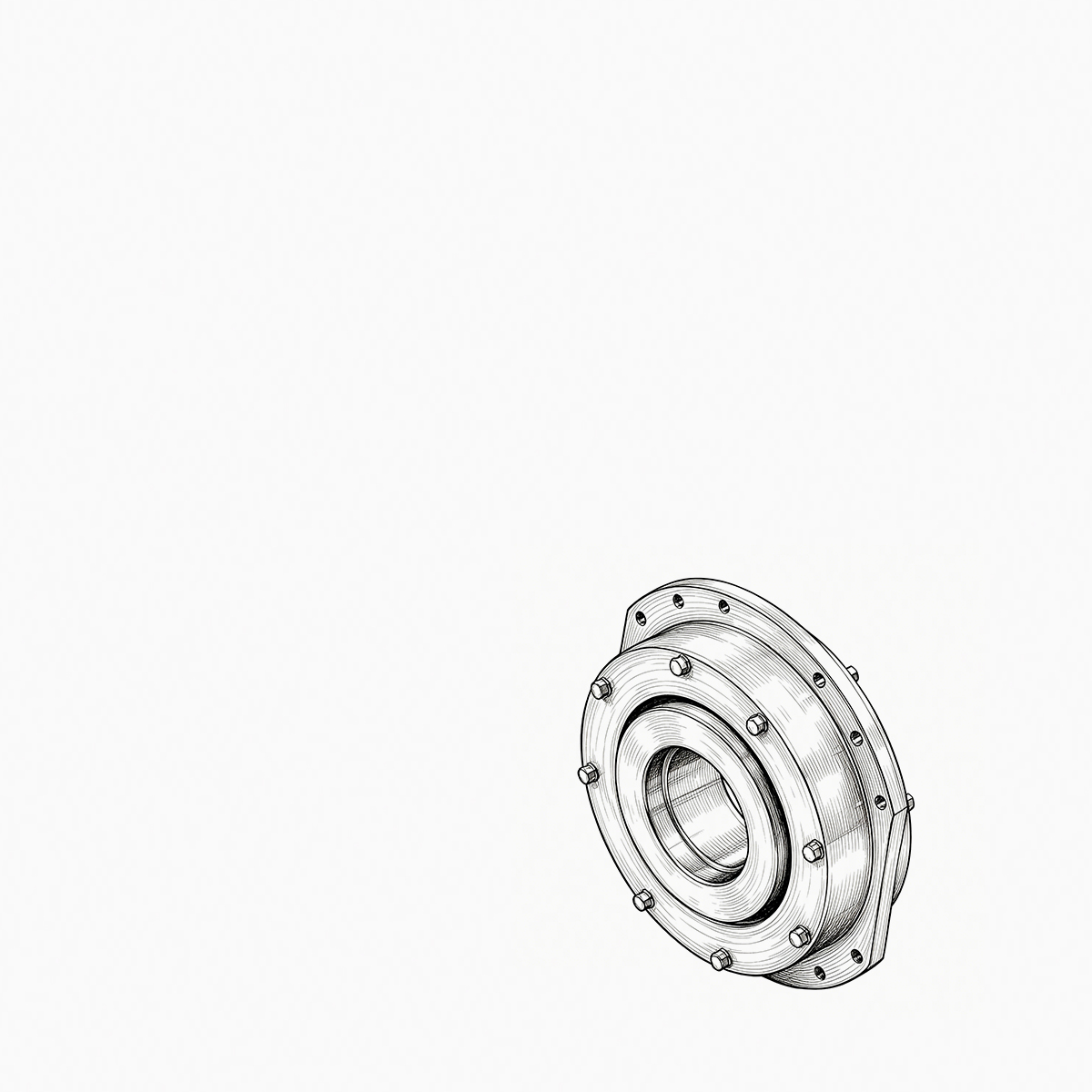
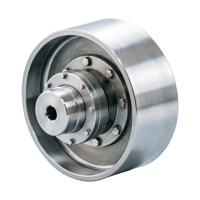
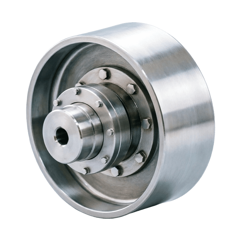 WGZ Crowned-Gear Coupling with Integrated Brake WheelConsider this brake-integrated coupling for hoisting and conveying drives needing compact braking, torque transmission, and attention to vertical-shaft lubrication and seal arrangement.View Product →
Vertical shafts add a second concern: lubrication. A vertically mounted crown gear coupling needs oil or grease to stay in the tooth mesh under gravity, so the fill level, the drain position and the seal arrangement all change compared with a horizontal unit.
Bore, Keyway and Balance Tolerances That Cause Rework
Most drum gear coupling returns have nothing to do with the teeth. They come from fits that were assumed instead of measured:
- Bore fit. A standard clearance fit slides onto a ground shaft end, but a worn shaft measuring a few hundredths over nominal will not. Measure the actual shaft, not the drawing.
- Keyway dimensions. Keyway width and depth tolerances differ between metric standards, and a key that is nominally correct but in the wrong tolerance class produces a rocking hub.
- Runout. Check hub radial runout after mounting; a coupling that runs true on the bench can show visible runout once the key seats.
- Balance. High-speed drives need a stated balance grade, and spacer types need the spacer balanced as part of the assembly, not separately.
None of these items adds cost at the quotation stage. All of them add cost after the coupling arrives.
Matching the Coupling Family to the Duty
Industrial drives rarely need an exotic coupling; they need the right variant of a familiar one. The table below maps common requests to the family that normally answers them.
| Family | Structure | Typical duty | Check before ordering |
|---|---|---|---|
| WG, GICL, GIICL | Crowned external teeth, bolted flange sleeves | Conveyors, pumps, mixers, general horizontal drives | Lubricant type and seal class |
| NGCL | Crowned teeth, heavy general duty | Mill auxiliaries, high-torque drives | Peak torque factor and duty cycle |
| GCLD | Straight cylindrical teeth | Well-aligned, cost-sensitive drives | Tighter alignment window |
| WGT | Crowned teeth with intermediate spacer | Pump and gearbox drop-out positions | Spacer length and balance grade |
| WGZ, WGP, NGCLZ | Crowned teeth with brake wheel or disc | Crane travel, hoists, positioning axes | Brake face dimensions and side |
| WGC | Crowned teeth, vertical mounting | Vertical pumps and agitators | Oil retention and drain position |
Duty still follows the industry. Steel mills, marine drives, petrochemical plants, mines and power stations all impose different shock, temperature and contamination profiles on the same hardware, and hoisting and construction machinery applications place the hardest demands on brake-integrated designs, because there the coupling is part of the stopping system rather than only the driving system.
A Short Procurement Checklist
- Record real shaft diameters, keyway dimensions and shaft end distances on both sides of the drive.
- Measure angular and parallel misalignment hot and cold, then add the thermal growth allowance.
- State lubricant grade, seal type and replenishment interval in operating hours.
- Confirm spacer length, brake interface geometry and mounting orientation on a dimensional drawing.
- Agree a balance grade for any drive running above roughly 1,500 rpm.
- Order spare sleeves and seal kits before the first shutdown, not after it.
A drum gear coupling is one of the few driveline components where a five-minute specification change produces a measurable difference in service life. Get the crown, the seal and the lubrication interval right, and the coupling will outlast several maintenance cycles on the same drive. Get them wrong, and it becomes an annual line item that nobody can quite explain.
PREV: How to Select Industrial Coupling Suppliers: Key Criteria for ReliabilityNEXT: Gear Coupling Manufacturers: How to Choose a Reliable Industrial Supplier
Be the First to Know
For exclusive deals and latest offers, sign up by entering your email address below.
Related products
News
-
-
Gear Coupling vs. Drum Gear Coupling: The Core Difference The main difference is that "gear coupling" is a broad catego...
READ MORE -
During a routine vibration survey on a high-speed compressor train, engineers found a 4.5 mm/s velocity spike at the mo...
READ MORE -
A maintenance engineer pulls a failed coupling from a pump drive. The elastomer sleeves are cracked, the pin bolts are ...
READ MORE -
Two quotes land for the same replacement gear coupling: $1,850 from one shop and $2,600 from another. Both promise stan...
READ MORE -
China's coupling industry is at a critical historical juncture of transformation from scale expansion to quality and eff...
READ MORE


ABOUT US
PRODUCTS
INDUSTRIES
CONTACT US
- Phone: +86-18652865511
- Email: sales@ohmach.com
- Address: No.1, Minying Developing Zone, Zhenjiang, Jiangsu, China
Copyright Zhenjiang Orienthold Machinery Co., Ltd. All Rights Reserved.
 Custom Industrial Shaft Coupling Manufacturers